Method for monitoring grounding current of main transformer iron core

A technology of iron core grounding current and main transformer, applied in the direction of measuring current/voltage, instruments, measuring devices, etc., can solve problems such as transformer tripping, transformer oil performance degradation, burnout, etc.

Inactive Publication Date: 2017-11-21
FOSHAN POWER SUPPLY BUREAU GUANGDONG POWER GRID
View PDF7 Cites 2 Cited by
  • Summary
  • Abstract
  • Description
  • Claims
  • Application Information

AI Technical Summary

Problems solved by technology

[0002] In order to prevent the floating potential in the iron core or other metal components due to electrostatic induction during the operation of the transformer, the transformer must be grounded and only one point can be grounded. If the iron core is grounded at multiple points, it will cause: (1) Local overheating of the iron core , so that the loss of the iron core increases, or even burns out; (2) The temperature rise caused by overheating causes the transformer oil to decompose, and the gas produced dissolves in the oil, causing the performance of the transformer oil to decline, and the total hydrocarbons in the oil greatly exceed the standard
(3) The gas in the oil continues to increase and precipitate, which may cause the gas relay to signal and even trip the transformer
At present, all transformer iron cores are directly grounded, and the current of the iron core can only be monitored by a clamp meter

Method used


Image

  • Method for monitoring grounding current of main transformer iron core
  • Method for monitoring grounding current of main transformer iron core
  • Method for monitoring grounding current of main transformer iron core

Examples


Embodiment 1

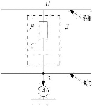
[0019] like figure 1 As shown, the main transformer includes a winding and an iron core, and an ammeter can be connected in series between the iron core and the ground. The voltage U on the winding is coupled to the iron core through a resistor R and a capacitor C, and then enters the ground through the ammeter, I=U / Z, The ground current of the iron core is monitored by an ammeter.

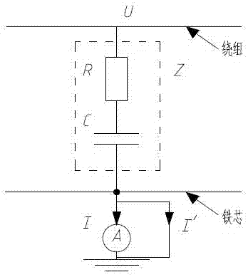
[0020] During normal operation, Z is very large, that is, the current passing through the ammeter is very small, generally tens of milliamperes. When the insulation between the winding and the iron core is damaged, that is, Z decreases and I increases. When the iron core is grounded at multiple points or the insulation between the iron core and the ground is reduced, the schematic diagram is as follows: figure 2 As shown, due to the shunting of the branch, the current flowing through the ammeter will decrease. Therefore, the reading of the ammeter can be used to judge whether the insulation ...

Embodiment 2

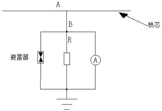
[0022] In the first embodiment, if figure 2 As shown, when the ammeter breaks inside, the iron core will lose its grounding, and a pair of ground potentials will be generated, and a floating discharge will occur at point B. In order to avoid this phenomenon, a resistor with a small resistance can be connected in parallel between the ammeters, the resistance value is close to the internal resistance of the ammeter, and a low-voltage arrester can be connected in parallel, such as image 3 shown.

[0023] The arrester presents a high-resistance state at low voltage, which is equivalent to an open circuit, that is, in normal operation, no current flows through the arrester, and the grounding current of the iron core is divided into two parts: one part passes through the parallel resistance R, and the other part passes through the ammeter, so as long as you know the parallel connection The resistance value and the internal resistance of the ammeter can accurately calculate the gr...


PUM


Abstract

The invention provides a method for monitoring grounding current of a main transformer iron core. The main transformer includes a winding and an iron core, and is characterized in that an ampere meter is connected between the iron core and the ground in series, voltage U on the winding is coupled to the iron core through a resistor R and a capacitor C, and enters to the ground through the ampere meter, grounding current of the iron core is monitored through the ampere meter, and the problem of a large error when current of an iron core is monitored through a clamp meter traditionally is solved.

Description

technical field [0001] The present invention relates to the technical field of main transformer monitoring, and more specifically, to a monitoring method for main transformer iron core grounding current. Background technique [0002] In order to prevent the floating potential in the iron core or other metal components due to electrostatic induction during the operation of the transformer, the transformer must be grounded and only one point can be grounded. If the iron core is grounded at multiple points, it will cause: (1) Local overheating of the iron core , so that the loss of the iron core increases, or even burns out; (2) The temperature rise caused by overheating causes the transformer oil to decompose, and the gas produced dissolves in the oil, causing the performance of the transformer oil to decline, and the total hydrocarbons in the oil greatly exceed the standard. (3) The gas in the oil continues to increase and precipitate, which may cause the gas relay to signal ...

Claims


Application Information

Patent Timeline
Patent Type & Authority Applications(China)
IPC IPC(8): G01R19/00
CPCG01R19/00
Inventor 洪贞贤
Owner FOSHAN POWER SUPPLY BUREAU GUANGDONG POWER GRID
Why Eureka
Try Eureka