Luneberg lens antenna

A Lumber lens antenna and antenna technology, applied to antennas, folded antennas, antenna supports/mounting devices, etc., can solve the problems of no advantages, high servo control power, etc., and achieve improved tracking ability, large beam deflection, and novel structure Effect

Active Publication Date: 2017-11-21
NO 54 INST OF CHINA ELECTRONICS SCI & TECH GRP
View PDF4 Cites 4 Cited by
  • Summary
  • Abstract
  • Description
  • Claims
  • Application Information

AI Technical Summary

Problems solved by technology

In this system, when the antenna is scanning the beam, it is necessary to set up an azimuth-elevation two-dimensional mount for the antenna to realize the two-dimensional scanning of the beam. This method requires a large servo control power. When performing fast beam pointing , with no apparent advantage

Method used


Image

  • Luneberg lens antenna
  • Luneberg lens antenna

Examples


Embodiment Construction

[0019] In order to make it easier for those skilled in the art to understand the technical solution of this patent, and at the same time, in order to make the technical purpose, technical solution and beneficial effect of this patent clearer, and to fully support the protection scope of the claims, the following is a specific case in the form of this patent. The technical solution of the patent makes further and more detailed descriptions.

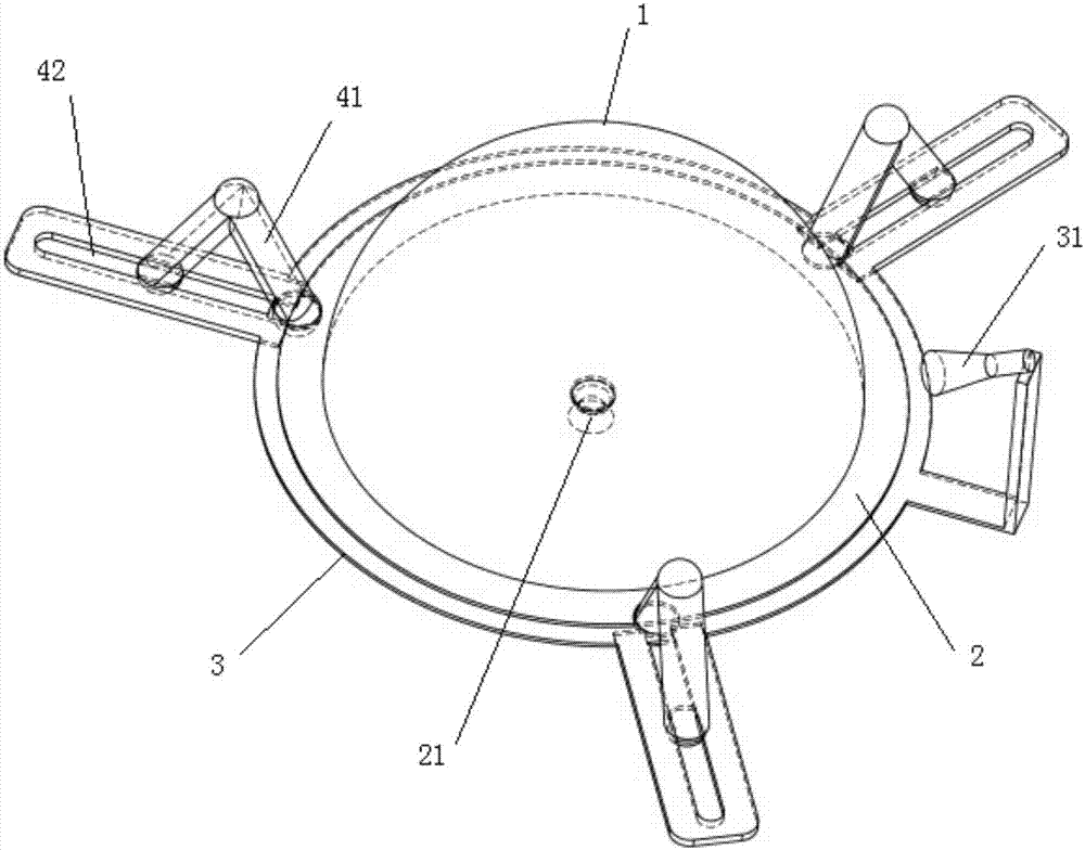
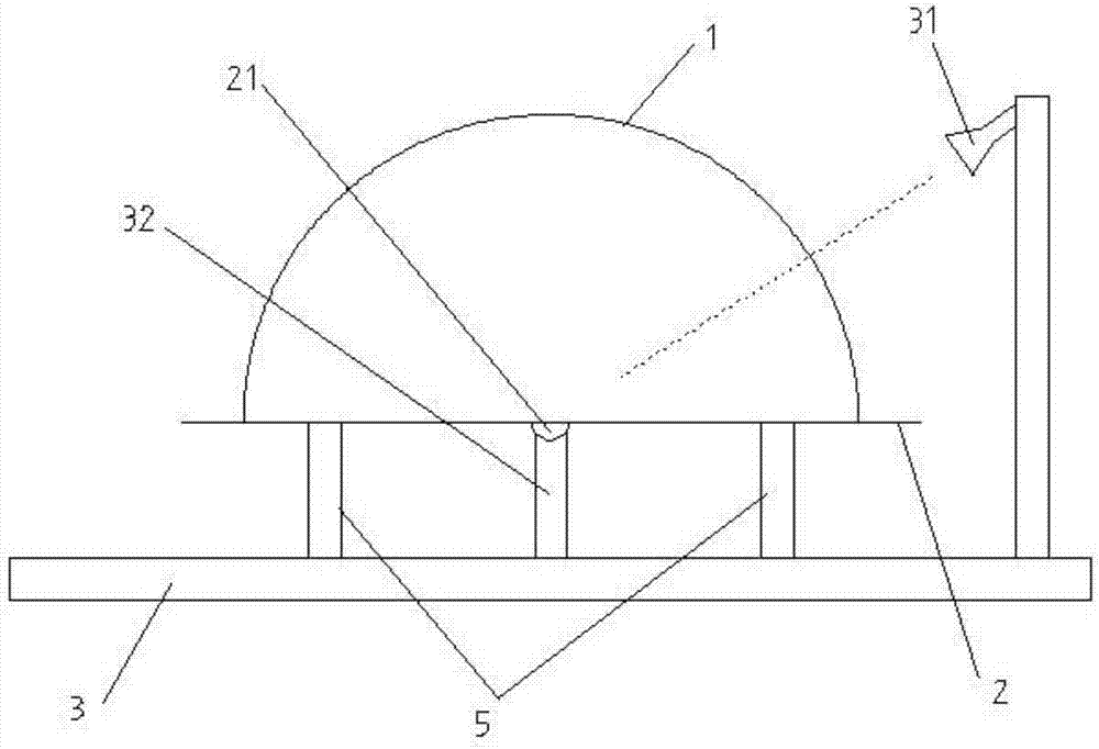
[0020] Such as figure 1 As shown, a Lunberg lens antenna includes an antenna bracket 3 and an antenna body arranged on the antenna bracket 3. The antenna body includes a reflection base plate 2 and a hemispherical lens 1, and the lens 1 is arranged on the reflection surface of the reflection base plate 2. A universal joint 21 located at the center of the lens 1 is provided on the back of the reflection base plate 2, a support body and a feed source 31 with a fixed position and pointing to the center of the lens 1 are provided on the antenn...


PUM


Abstract

The invention discloses a Luneberg lens antenna, and belongs to the technical field of antennas. The Luneberg lens antenna comprises an antenna support and an antenna body, wherein the antenna body is arranged on the antenna support and comprises a reflective bottom plate and a semi-spherical lens, the lens is arranged on a reflective surface of the reflective bottom plate, an universal joint is arranged on a back surface of the reflective bottom plate and is arranged at a central position of the lens, a support body and a feeding source are arranged on the antenna support, the position of the feeding source is fixed, the feeding source points to a sphere center of the lens, the antenna body is connected with the support body via the universal joint, and a mechanical structure is also arranged on the antenna support and is used for pushing the antenna body so that the antenna body rotates by taking the universal joint as a center. The Luneberg lens antenna has the characteristics of a novel structure, high tracking capability and low profile, is convenient to use and is an important improvement of the prior art.

Description

technical field [0001] The invention relates to the technical field of antennas, in particular to a Lunberg lens antenna. Background technique [0002] In electronic information systems, traditional lens antennas can be used to perform beam scanning in a variety of ways, each of which has its own characteristics, specifically as follows: [0003] 1. The feed source moves in two dimensions while the lens does not move. The beam scanning of this method is relatively simple. A mechanical arm that can rotate in azimuth is set on the edge of the bottom plate of the lens. The feed source is mounted on the mechanical arm, and the feed source can move radially along the mechanical arm. When the manipulator and the feeder move in azimuth, azimuth beam scanning can be realized. When the feed source moves along the radial direction of the manipulator, the elevation beam can be scanned. The beam scanning in this way is relatively simple, but the mechanical motion requires two-dimensi...

Claims


Application Information

Patent Timeline
Patent Type & Authority Applications(China)
IPC IPC(8): H01Q1/10H01Q1/12H01Q15/23
CPCH01Q1/10H01Q1/12H01Q15/23Y02D30/70
Inventor 韩国栋张立军段永强
Owner NO 54 INST OF CHINA ELECTRONICS SCI & TECH GRP
Why Eureka
Try Eureka