
Integrated directional antenna

A directional antenna and antenna radiator technology, applied in the direction of resonant antenna, antenna grounding device, antenna grounding switch structure connection, etc., can solve the problems of large reflection coefficient, low profile, low overall antenna efficiency, etc., to achieve simplified structure and high orientation Effect of radiation, high radiation efficiency

Active Publication Date: 2020-11-10
HANGZHOU HIKVISION DIGITAL TECH
View PDF8 Cites 0 Cited by
  • Summary
  • Abstract
  • Description
  • Claims
  • Application Information

AI Technical Summary

Problems solved by technology

[0003] Although the above scheme can obtain the required directional radiation antenna to a certain extent, when the antenna is too close to the metal reflector, a part of the energy will be offset due to the difference in the phase of the reflected electromagnetic wave, resulting in a very low overall efficiency of the antenna and a very low reflection coefficient. Big
In order to improve the radiation efficiency of the directional antenna, the distance between the antenna and the metal plate should be set to about 1 / 4 of the working wavelength, but this makes the antenna incompatible with the low profile and miniaturization required in the development of microwave communication

Method used


Image

  • Integrated directional antenna
  • Integrated directional antenna
  • Integrated directional antenna

Examples


Embodiment 1

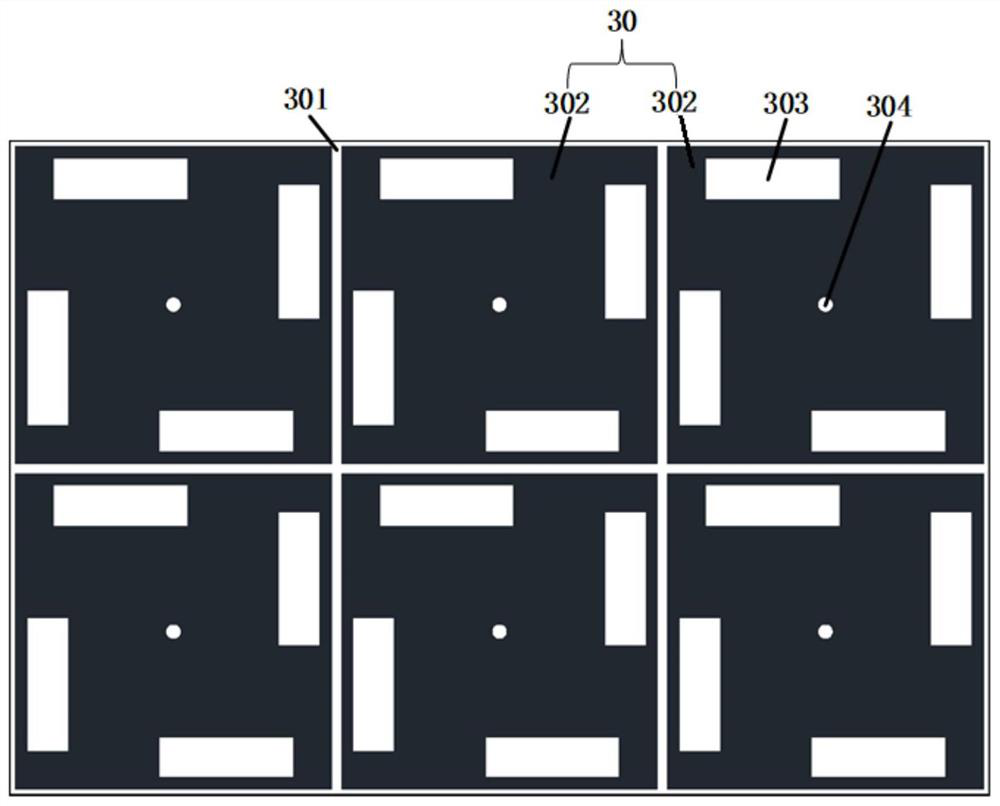
[0059] Such as Figure 4 As shown, on each metal patch unit 302 , there are multiple slots 303 , and the multiple slots 303 are distributed around the metal via hole 304 .

[0060] A plurality of grooves 303 are rectangular grooves, and each metal patch unit 302 is provided with four rectangular grooves, and the four rectangular grooves are arranged around the metal via hole 304. On each metal patch unit 302, two adjacent The length direction of the rectangular groove is vertical.

[0061] It should be noted that the postures of the rectangular slots on each metal patch unit 302 may be different, for example, the rectangular slots may be inclined at a preset angle relative to the horizontal direction or the vertical direction, and the like.

Embodiment 2

[0063] Such as Figure 5 As shown, on each metal patch unit 302 , there are multiple slots 303 , and the multiple slots 303 are distributed around the metal via hole 304 .

[0064] The plurality of grooves 303 are arc-shaped strip-shaped grooves, and each metal patch unit 302 is respectively provided with four arc-shaped strip-shaped grooves, and the four arc-shaped strip-shaped grooves are arranged around the metal via hole 304, and each The centers of the arc-shaped strip grooves coincide.

Embodiment 3

[0066] Such as Figure 6 As shown, on each metal patch unit 302 , there are multiple slots 303 , and the multiple slots 303 are distributed around the metal via hole 304 .

[0067] The plurality of grooves 303 are arc-shaped strip-shaped grooves, and each metal patch unit 302 is respectively provided with four arc-shaped strip-shaped grooves, and the four arc-shaped strip-shaped grooves are arranged around the metal via hole 304, and each The center of the arc-shaped strip groove coincides with the center of the metal via hole 304 .


PUM


Abstract

The invention provides an integrated directional antenna. The antenna comprises a first dielectric substrate which comprises an antenna radiator arranged on the upper surface, wherein the antenna radiator is in feed connection with a signal emission source and is connected with a ground point; and a second dielectric substrate which comprises an EBG metal patch arranged on the upper surface and afloor layer arranged on the lower surface, wherein the EBG metal patch is connected with the floor layer through a metal via hole. The lower surface of the first dielectric substrate and the upper surface of the second dielectric substrate are jointed to form an integrated laminated structure, and the outer contour of the EBG metal patch surrounds the outer contour of the antenna radiator in the projection along the direction perpendicular to the first dielectric substrate and the second dielectric substrate. According to the antenna, the high gain, high radiation efficiency, low profile and miniaturization are realized, and in addition, the first dielectric substrate and the second dielectric substrate which are of the integrated structure omit a fixing structure for keeping mutual relative fixation, so that the structure of the antenna is simplified.

Description

technical field [0001] The present application relates to the technical field of wireless communication, and in particular, relates to an integrated directional antenna. Background technique [0002] In wireless communication systems, there are many bidirectional radiation antennas, such as aperture antennas, equiangular helical antennas, slot antennas, dipole antennas, Archimedes helical antennas, etc. In order to achieve directional radiation of antennas, in the prior art, Usually, a metal reflector is loaded on the back of the antenna to reflect the radiated electromagnetic wave to ensure the directivity of the antenna radiation. [0003] Although the above scheme can obtain the required directional radiation antenna to a certain extent, when the antenna is too close to the metal reflector, a part of the energy will be offset due to the difference in the phase of the reflected electromagnetic wave, resulting in a very low overall efficiency of the antenna and a very low r...

Claims


Application Information

Patent Timeline
Patent Type & Authority Applications(China)
IPC IPC(8): H01Q1/38H01Q1/48H01Q1/50H01Q9/04
CPCH01Q1/38H01Q1/48H01Q1/50H01Q9/0407
Inventor 李峙
Owner HANGZHOU HIKVISION DIGITAL TECH
Learn More