Sawtooth wave generation circuit and flyback, sepic and buck-boost power factor correction converters

A technology for generating circuits and sawtooth waves, which is applied to output power conversion devices, pulse generation, high-efficiency power electronic conversion, etc., can solve the problem of large peak current of the converter, increased conduction loss of the main switch tube, and failure to obtain unit power factor And other issues

Active Publication Date: 2019-12-31
XIHUA UNIV
View PDF6 Cites 0 Cited by
  • Summary
  • Abstract
  • Description
  • Claims
  • Application Information

AI Technical Summary

Problems solved by technology

The peak current of the flyback power factor correction converter in discontinuous conduction mode is very large, which increases the conduction loss of the main switch and affects the efficiency of the converter
However, the traditional critical continuous mode flyback, Buck-Boost and SEPIC power factor correction converters have higher efficiency than discontinuous mode converters, but they cannot obtain unity power factor, and their power factor and total harmonic distortion are worse than discontinuous mode converters.

Method used


Image

  • Sawtooth wave generation circuit and flyback, sepic and buck-boost power factor correction converters
  • Sawtooth wave generation circuit and flyback, sepic and buck-boost power factor correction converters
  • Sawtooth wave generation circuit and flyback, sepic and buck-boost power factor correction converters

Examples


Embodiment Construction

[0023] The following will clearly and completely describe the technical solutions in the embodiments of the present invention with reference to the accompanying drawings in the embodiments of the present invention. Obviously, the described embodiments are only some, not all, embodiments of the present invention. Based on the embodiments of the present invention, all other embodiments obtained by persons of ordinary skill in the art without making creative efforts belong to the protection scope of the present invention.

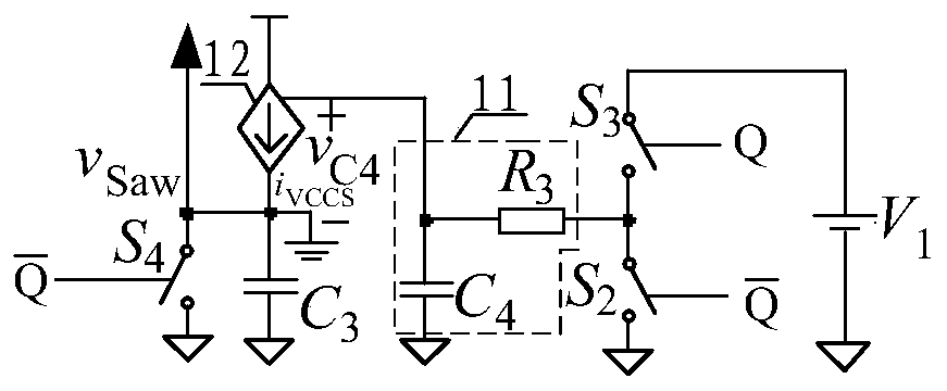
[0024] The embodiment of the present invention discloses a variable slope sawtooth wave generation circuit, see figure 1 shown, the circuit includes: a voltage source V 1 , the first switch S 2 , the second switch S 3 , the third switch S 4 , low-pass filter 11, voltage-controlled current source 12 and capacitor C 3 ; Among them, the voltage source V 1 Positive and second switch S 3 The first end of the connection, the second switch S 3 The control term...


PUM


Abstract

The invention discloses a variable-slope sawtooth wave generation circuit, a flyback power factor correction converter, a SEPIC power factor correction converter, and a Buck-Boost power factor correction converter. The sawtooth wave generation circuit comprises a voltage source anode connected with a first end of a second switch. A control end of the second switch is connected with a Q end of an RS trigger. A second end of the second switch, an input end of a low pass filter, and a first end of a first switch are interconnected. The control end of the first switch is connected with a Q<-> end of the RS trigger. The output end of the low pass filter is connected with a voltage control end anode of a voltage control current source. The output end of the voltage control current source, one end of a capacitor, a first end of a third switch, and a positive input end of a comparator are interconnected. A control end of the third switch is connected with the Q<-> end of the RS trigger, and the rest ports are connected with ground. Sawtooth wave gradient is controlled by turn-on time and turn-off time of a main switch tube of critical continuous mode power factor correction converter, a PWM wave is modulated, and a power factor of the power factor correction converter is improved.

Description

technical field [0001] The invention relates to the technical field of power electronics, in particular to a variable-slope sawtooth wave generation circuit, a flyback power factor correction converter, a SEPIC power factor correction converter and a Buck-Boost power factor correction converter. Background technique [0002] In recent years, power electronics technology has developed rapidly, and power supply technology, which is an important part of the power electronics field, has gradually become a hot spot in application and research. Switching power supply has established its mainstream position in the field of power supply because of its high efficiency and high power density, but there will be a fatal weakness when it is connected to the power grid through a rectifier: the power factor is low (generally only 0.45 to 0.75), Moreover, a large number of current harmonics and reactive power will be generated in the grid to pollute the grid. There are two main methods of ...

Claims


Application Information

Patent Timeline
Patent Type & Authority Patents(China)
IPC IPC(8): H02M1/42H03K4/50H03K7/08
CPCH02M1/42H03K4/50H03K7/08Y02B70/10
Inventor 阎铁生王军沈霞曹太强孙章陶权保李明洪杨坤
Owner XIHUA UNIV
Why Eureka
Try Eureka