Data transmission method, device and system

A transmission method and data technology, applied in the field of communication, can solve the problems of out-of-order data packets and no solution.

Inactive Publication Date: 2017-11-21
ZTE CORP
View PDF1 Cites 4 Cited by
  • Summary
  • Abstract
  • Description
  • Claims
  • Application Information

AI Technical Summary

Problems solved by technology

[0004] In order to support the ONU to transmit data exceeding the rate of a single channel, it is proposed that the ONU can support simultaneous transmission and reception of data on multiple wavelength channels. Under this architecture, how does the OLT send data to multiple wavelength channels and send it to the ONU? For the problem of how to combine the data packets according to the order sent by the OLT after the ONU receives them, in the related art, the data packets are numbered by the OLT, and the numbers are inserted into the frame structure containing the data packets, but in the existing PON system There is not enough space in the frame structure to carry the number of this data packet. If the data packets are sent to the ONU in a certain time order, then if the data link is jittered, the data packet sent first will be later than the data packet sent later. Arriving at the receiving end, it will cause the receiver's data packets to be out of order
[0005] For the above-mentioned problems in related technologies, there is no effective solution yet

Method used


Image

  • Data transmission method, device and system
  • Data transmission method, device and system
  • Data transmission method, device and system

Examples


Embodiment 1

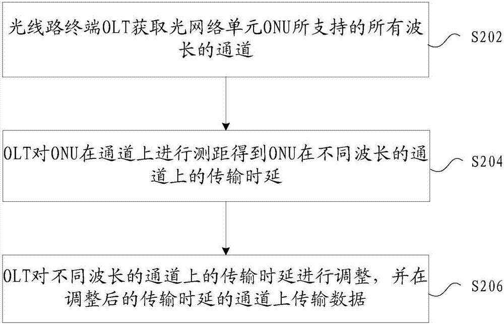
[0040] figure 2 It is the flow of the data transmission method according to the embodiment of the present invention Figure 1 ,like figure 2 As shown, the steps of the method include:

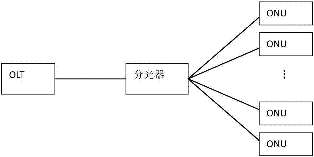
[0041] Step S202: the optical line terminal OLT obtains channels of all wavelengths supported by the optical network unit ONU;

[0042] Step S204: The OLT performs ranging on the channel to the ONU to obtain the transmission delay of the ONU on channels of different wavelengths;

[0043] Step S206: The OLT adjusts the transmission delays on the channels of different wavelengths, and transmits data on the channels with the adjusted transmission delays;

[0044] Wherein, the adjusted transmission delay makes the time required for data transmitted on all channels of the OLT to reach the ONU equal. For example, shorten or extend the transmission time, or adjust the transmission time delay to be consistent with other transmission time delays.

[0045] Through the above steps S202 to S206, the...

Embodiment 2

[0063] Embodiment 2 corresponds to Embodiment 1, Embodiment 1 is described from the OLT side, and Embodiment 2 is described from the ONU side;

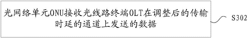
[0064] image 3 It is the flow of the data transmission method according to the embodiment of the present invention Figure II ,like image 3 As shown, the steps of the method include:

[0065] Step S302: the optical network unit ONU receives the data sent by the optical line terminal OLT on the channel with the adjusted transmission delay;

[0066] Wherein, the adjusted transmission delay makes the time required for the data sent on all channels of the OLT to reach the ONU equal.

[0067] For this step S302, the optical network unit ONU receives the data sent by the optical line terminal OLT on the channel of the adjusted transmission delay, which can be realized in the following manner:

[0068] Step S302-1: The ONU packs the data of multiple channels according to the order of the receiving time of the first bit of each received...

Embodiment 3

[0073] Figure 4 is the structural frame of the data transmission device according to the embodiment of the present invention Figure 1 , the device is applied to the OLT side of the optical line terminal, such as Figure 4 As shown, the device includes: an acquisition module 42, used to acquire the channels of all wavelengths supported by the optical network unit ONU; a ranging module 44, coupled with the acquisition module 42, used to perform ranging on the channel to the ONU to obtain the ONU Transmission time delay on channels of different wavelengths; the first transmission module 46 is coupled with the ranging module 44, and is used to adjust the transmission time delay on channels of different wavelengths, and adjust the transmission time delay in the channel upload data;

[0074] Wherein, the adjusted transmission delay makes the time required for data transmitted on all channels of the OLT to reach the ONU equal.

[0075] Optionally, the device in this embodiment m...


PUM


Abstract

The invention provides a data transmission method, device and system. The data transmission method comprises that an optical line terminal (OLT) acquiring all wavelength channels supported by an optical network unit (ONU); the OLT performs ranging on the ONU on the channels to obtain transmission delays of the ONU on different wavelength channels; and the OLT adjusts the transmission delays on the different wavelength channels and transmits data on the channels with the adjusted transmission delays, wherein the adjusted transmission delays enable the data transmitted on all channels of the OLT to require the same time to reach the ONU. According to the invention, a problem in the related art that disorder occurs when data is sent or received on multiple groups of wavelength channels is solved.

Description

technical field [0001] The present invention relates to the communication field, in particular, to a data transmission method, device and system. Background technique [0002] With the development of network technology, the network can be used to transmit a large amount of voice, data, video and other services, so the requirements for bandwidth continue to increase. Passive Optical Network (PON) was born under this demand . [0003] The topology of the PON system is as follows figure 1 as shown, figure 1 It is a schematic diagram of the composition structure of the passive optical network in the related art. The PON system usually consists of an optical line terminal (Optical Line Terminal, referred to as OLT) on the office side, an optical network unit (Optical Network Unit, referred to as ONU) on the user side and optical distribution Network (Optical Distribution Network, ODN for short), usually using a point-to-multipoint network structure. ODN is composed of passive...

Claims


Application Information

Patent Timeline
Patent Type & Authority Applications(China)
IPC IPC(8): H04Q11/00H04J3/06
CPCH04Q11/00H04Q11/0005H04J3/0635H04Q2011/0045
Inventor 耿丹张伟良袁立权马壮郭勇
Owner ZTE CORP
Why Eureka
Try Eureka