Automatic batch skewering machine

A stringer and batch technology, which is applied in the direction of skewering meat onto meat skewers, meat processing equipment, slaughtering, etc., can solve the problems of high labor cost and time cost, difficulty in ensuring the hygiene and safety of skewered products, and low processing efficiency. , to achieve the effect of improving processing efficiency, saving time and labor costs, and saving processing space

Inactive Publication Date: 2017-11-24
王海石
View PDF7 Cites 3 Cited by
  • Summary
  • Abstract
  • Description
  • Claims
  • Application Information

AI Technical Summary

Problems solved by technology

[0004] The purpose of the present invention is to solve the problems of low processing efficiency, high labor cost and time cost, high labor intensity, and diff...

Method used


Image

  • Automatic batch skewering machine
  • Automatic batch skewering machine
  • Automatic batch skewering machine

Examples


specific Embodiment approach 1

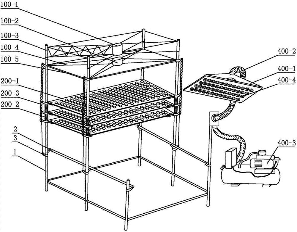
[0025] Specific implementation mode one: combine figure 1 , figure 2 , Figure 14 and Figure 15 Describe this embodiment, an automatic batch threading machine of this embodiment, which includes a bracket 1, a hydraulic cylinder, a sign pushing device, a sign limiting device, a material suction device, two template slides 2, a plurality of curved arms 3 and Multiple sets of material setting templates, sign pushing device, sign limiting device and multiple sets of material setting templates are arranged on the support 1 in sequence from top to bottom, the suction device is installed on the side column of the support 1, and the sign pushing device includes the upper chamber of the oil cylinder 100 -1, oil cylinder lower chamber 100-2, upper chamber support 100-3, lower chamber support 100-4 and sign pushing plate 100-5, the four bushings of the upper chamber support 100-3 are set on the four vertical supports of the support 1 The upper end of the rod is fixedly connected to ...

specific Embodiment approach 2

[0028] Specific implementation mode two: combination figure 1 and Figure 16 Describe this embodiment, the suction device of this embodiment includes negative pressure suction pan 400-1, negative pressure suction universal arm 400-2 and negative pressure vacuum suction pump 400-3, negative pressure suction pan 400- The lower end surface of 1 is provided with a plurality of suction holes 400-4 in a rectangular array, the negative pressure suction universal arm 400-2 is a hollow tubular universal arm, and one end of the negative pressure suction universal arm 400-2 is connected to the The upper end of the negative pressure suction tray 400-1 is connected, and the other end of the negative pressure suction universal arm 400-2 is connected with the negative pressure vacuum suction pump 400-3. With such a setting, using the suction device instead of the traditional manual placement of string products into the material placement template, on the one hand, the processing efficiency ...

specific Embodiment approach 3

[0029] Specific implementation mode three: combination Figure 8 Describe this embodiment, this embodiment also includes a first sign setting device, the first sign setting device includes a sign setting plate 500-1, a first handle 500-2, a first inner handle 500-3, a connecting rod 500-4, a spring and a plurality of clamping rods 500-5, the first handle 500-2 is installed on one end of the signing board 500-1, and the connecting rod 500-4 is inserted in the signing board 500 along the longitudinal axis N-N direction of the signing board 500-1 -1, one end of the connecting rod 500-4 is affixed to the spring, the other end of the spring is affixed to the sign setting plate 500-1, the first inner handle 500-3 is installed on the other end of the connecting rod 500-4, and the sign setting plate The upper end surface of 500-1 is evenly provided with a plurality of lottery slots 500-6, and the plurality of lottery slots 500-6 are all perpendicular to the longitudinal axis N-N of th...


PUM


Abstract

The invention discloses an automatic batch skewering machine, relates to the field of food processing and aims at solving the problems of low processing efficiency, high human cost, high time cost, large labor intensity and difficulty in ensuring sanitary safety of string products in the existing skewering process of the string products. A prod pushing device, a prod limiting device and a plurality of groups of material placing templates are sequentially arranged on a bracket from top to bottom; a material sucking device is installed on an upright column on the side surface of the bracket; four bushings of an upper chamber bracket sleeve the upper ends of four vertical rods of the bracket respectively; a lower chamber bracket is in sliding connection with the bracket; prod pushing plates are fixedly connected with the lower end of the lower chamber bracket; a hydraulic cylinder is installed in an oil cylinder upper chamber; a piston rod of the hydraulic cylinder is fixedly connected with an oil cylinder lower chamber; the prod limiting device is connected with the four vertical rods of the bracket in a sliding manner; two template slideways are fixedly connected with the lower part of the bracket through a plurality of bent arms respectively; and a plurality of groups of material placing templates are installed on the two template slideways in the sliding manner. The automatic batch skewering machine is used for skewering string products of meat strings, sugar-coated haws and the like.

Description

technical field [0001] The invention relates to the field of food processing, in particular to an automatic batch threading machine. Background technique [0002] With the improvement of people's living standards, the demand for meat products is also increasing. The existing stringing technology includes manual stringing and automatic stringing equipment. Manual stringing requires one by one. The threading system has low processing efficiency, high labor and time costs, high labor intensity, and it is difficult to ensure the hygiene and safety of the stringing products; while the existing automatic threading equipment is a single-layer material placement template structure, which adopts horizontal threading The method of threading and making string products requires manual placement of string products in the material placement template, which has the problems of low processing efficiency and high labor cost. When the processing demand of string products is very large, only m...

Claims


Application Information

Patent Timeline
IPC IPC(8): A22C17/00
CPCA22C17/006
Inventor 王海石
Owner 王海石
Why Eureka
Try Eureka