Auxiliary painting device for automobile parts

A technology for auto parts and spray paint cans, which is applied to spray devices, liquid spray devices, spray booths, etc., can solve the problems of inconvenient movement, adjustment, and harsh working environment for operators, so as to ensure work efficiency, improve adaptability and convenience. moving effect

Inactive Publication Date: 2017-11-24
JIANGSU KANGJIE MACHINERY
View PDF0 Cites 7 Cited by
  • Summary
  • Abstract
  • Description
  • Claims
  • Application Information

AI Technical Summary

Problems solved by technology

[0002] As we all know, the auxiliary painting device for auto parts is an auxiliary device for the surface painting treatment of auto parts in enterprises related to the production and processing of auto parts, and is widely used in the above-mentioned enterprises; the existing auxiliary painting device for auto parts includes base plate , placement rack, paint spray tank, delivery pipe and spray gun, the placement rack and paint spray tank are installed on the bottom plate, the input end of the delivery pipe is connected with the paint spray tank, the spray gun is installed at the output end of the delivery pipe, and a control device is set on the delivery pipe Pump; when using this auxiliary paint spraying device for auto parts, just place the auto parts on the shelf, and control the pump to control the spray gun to output the paint to complete the painting work; it is found in use that it is very inconvenient to move; and its spray paint The paint is scattered in the working environment, resulting in a poor working environment for the operators; and the height and angle of the rack cannot be adjusted, requiring the staff to move constantly to carry out the overall painting work, and the work efficiency cannot be guaranteed

Method used


Image

  • Auxiliary painting device for automobile parts

Examples


Embodiment Construction

[0015] The specific implementation manners of the present invention will be further described in detail below in conjunction with the accompanying drawings and embodiments. The following examples are used to illustrate the present invention, but are not intended to limit the scope of the present invention.

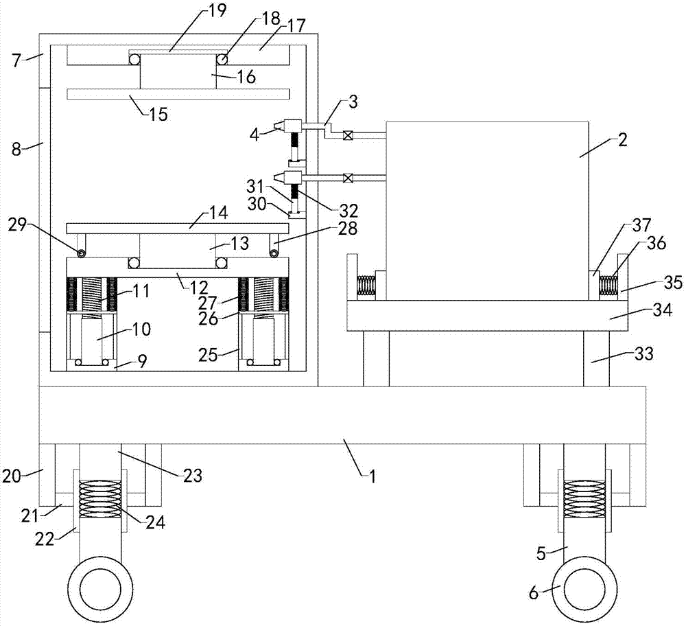
[0016] like figure 1 As shown, the auxiliary painting device for auto parts of the present invention includes a base plate 1, a placement frame, a paint spray can 2, a delivery pipe 3 and a spray gun 4, the input end of the delivery pipe communicates with the paint spray can, and the spray gun is installed at the output end of the delivery pipe, and A control pump is arranged on the conveying pipe; it also includes four sets of outriggers 5 and four sets of rollers 6. They are respectively installed under the four sets of supporting legs; also include a working box 7, the working box is installed on the bottom plate, the inside of the working box is provided with a workin...


PUM


Abstract

The invention relates to the technical field of painting devices, in particular to an auxiliary painting device for automobile parts. The auxiliary painting device for the automobile parts is easy to move, and working environment and working efficiency are guaranteed. The auxiliary painting device comprises a bottom plate, a placing frame, a painting tank, a conveying pipe and a spraying gun, four groups of landing legs, four groups of rollers and a working box, wherein a controlling pump is arranged on the conveying pipe, a working cavity is formed in the working box; a taking-placing opening is formed in the side wall of the working box, and a blocking cover is arranged at the position of the taking-placing opening; the placing frame comprises a left connecting plate, a left threaded pipe, a left threaded rod, a right connecting plate, a right threaded tube, a right threaded rod, a supporting plate, a lower rotating shaft, a supporting plate, a fixing plate, an upper rotating shaft and a top plate; and a left placing groove and a right placing groove are correspondingly formed in the top ends of the left connecting plate and the right connecting plate, a left rolling ball bearing and a right rolling ball bearing are correspondingly arranged in the left placing groove and the right placing groove, a lower placing groove is formed in the middle of the top end of the supporting plate, a lower rolling ball bearing is arranged in the lower placing groove, and an upper placing groove is formed in the bottom end of the top plate.

Description

technical field [0001] The invention relates to the technical field of painting devices, in particular to an auxiliary painting device for auto parts. Background technique [0002] As we all know, the auxiliary painting device for auto parts is an auxiliary device for the surface painting treatment of auto parts in enterprises related to the production and processing of auto parts, and is widely used in the above-mentioned enterprises; the existing auxiliary painting device for auto parts includes base plate , placement rack, paint spray tank, delivery pipe and spray gun, the placement rack and paint spray tank are installed on the bottom plate, the input end of the delivery pipe is connected with the paint spray tank, the spray gun is installed at the output end of the delivery pipe, and a control device is set on the delivery pipe Pump; when using this auxiliary paint spraying device for auto parts, just place the auto parts on the shelf, and control the pump to control th...

Claims


Application Information

Patent Timeline
Patent Type & Authority Applications(China)
IPC IPC(8): B05B13/02B05B15/12B05B9/04
CPCB05B9/0403B05B13/02B05B13/0278B05B16/80
Inventor 吴文杰吴进姜大林
Owner JIANGSU KANGJIE MACHINERY
Why Eureka
Try Eureka