Check patentability & draft patents in minutes with Patsnap Eureka AI!

Steelmaking continuous casting robot cutting system

A cutting system, steelmaking and continuous casting technology, applied in the field of steelmaking and continuous casting robot cutting system, can solve the problems of affecting cutting quality, increasing energy consumption, and short service life of cutting devices, so as to improve the cutting environment and avoid the problem of slag hanging , Improve the effect of cutting quality

Pending Publication Date: 2017-11-24
江西剑光节能科技有限公司
View PDF0 Cites 1 Cited by
  • Summary
  • Abstract
  • Description
  • Claims
  • Application Information

AI Technical Summary

Problems solved by technology

However, due to the unreasonable setting structure and setting method of the existing continuous casting cutting devices, the automatic cutting gun and the automatic ignition gun are installed on the cutting trolley through their respective mounting brackets without exception.
And its cutting trolley of all existing systems only has to be installed on the top of the cutting billet without exception.
Moreover, a bulky gantry frame is used to set it above the cut billet, which not only takes up a lot of space on the production site, but also because the temperature of the cut billet is very high, reaching thousands of degrees Celsius, and the heat basically goes to the The direct radiation on the upper part is transmitted to the cutting device such as the cutting car and the cutting gun and ignition gun on the car, which makes the service life of the cutting device short and the working stability is poor, especially the ignition reliability and stability of the ignition gun is poor.
In addition, the cutting method can only be cut from the top in the left and right directions.
The overall problem is: not only the cutting quality is seriously affected, a large amount of dross (commonly known as cutting fibroids) appears, energy consumption is increased, but also the maintenance and repair workload of the cutting system equipment is needlessly increased
As a result, the cost of cutting and continuous casting has increased unnecessarily

Method used


Image

  • Steelmaking continuous casting robot cutting system
  • Steelmaking continuous casting robot cutting system
  • Steelmaking continuous casting robot cutting system

Examples


Embodiment Construction

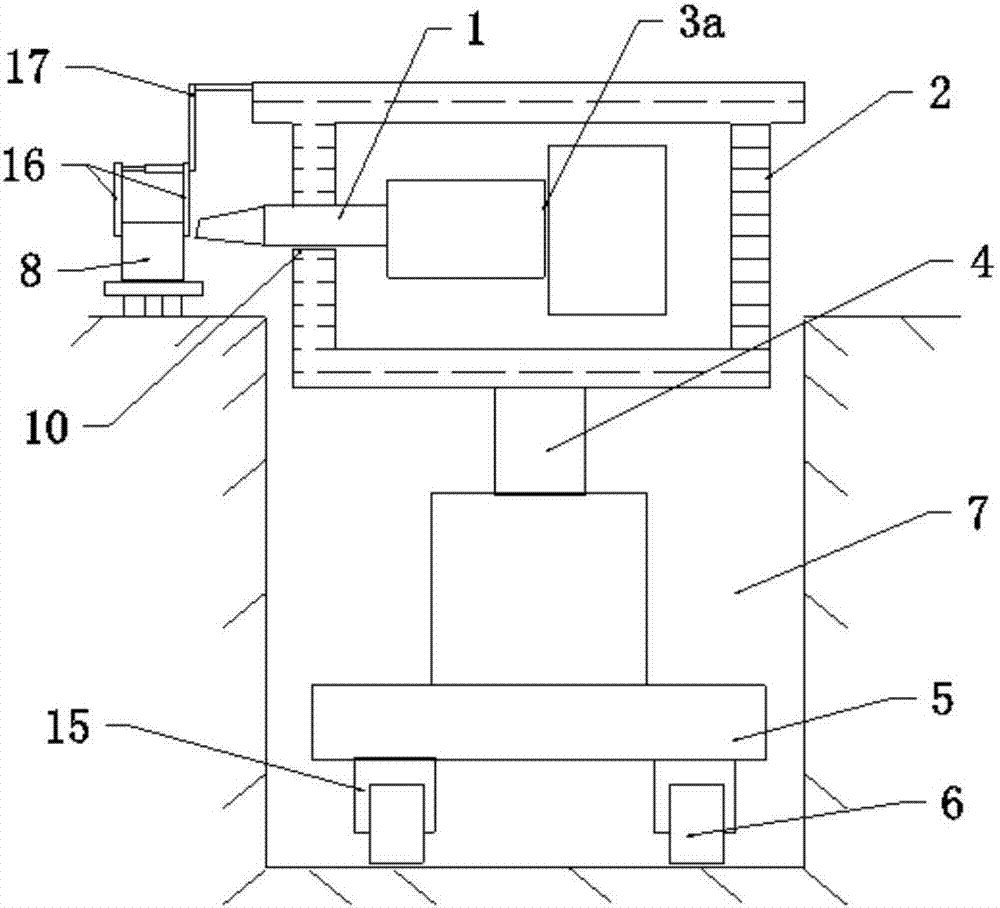
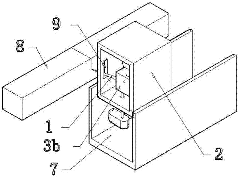
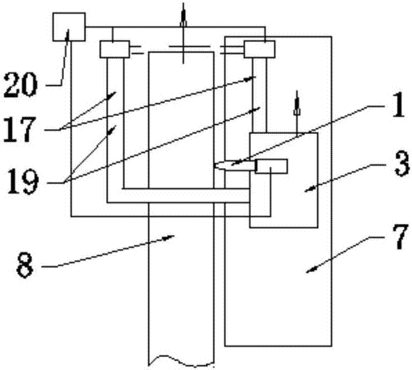
[0014] In order to further understand the technical solutions of the present invention, the present invention will be further described by the following embodiments in conjunction with the accompanying drawings. Such as figure 1 shown. The steelmaking and continuous casting robot cutting system of this embodiment includes trenches or ground passages 7 arranged on the corresponding side of the continuous casting billet along the output direction or length direction of the cut body (continuous casting billet) 8, the cutting robot and the Cutting robots and cutters for continuous casting billets, corresponding control systems, etc. The cutter includes a cutting gun, or includes a cutting gun and a corresponding ignition gun.

[0015] In the present invention, the cutting robot is placed on the corresponding side of the continuous casting billet, and the cutting tool can be extended to the upper, lower, left or right side wall of the continuous casting billet, that is, it can cu...


PUM


Abstract

The invention discloses a steelmaking and continuous casting robot cutting system, comprising a cutter, a corresponding control system and a guiding device, the cutter includes a cutting tool, and a signal connected to the control system for connecting or manipulating the cutting tool The corresponding cutting robot, the guiding device includes an action channel arranged on the corresponding side of the object to be cut, and the cutting robot is arranged on the action channel corresponding to the corresponding object to be cut. The steelmaking and continuous casting robot cutting system has a very simple structure, scientific and reasonable setting structure, and convenient installation. It can effectively solve the service life of cutting guns, cutting nozzles and ignition guns, and the installation and manufacturing costs of the entire system are low.

Description

technical field [0001] The invention relates to a steelmaking and continuous casting robot cutting system. Background technique [0002] In the production of steelmaking and continuous casting, the structure of the continuous casting cutting device, the corresponding cutting method, reliability and performance are important factors to improve the efficiency of steelmaking and continuous casting cutting production. To varying degrees, it affects not only the cutting speed, but also the energy consumption of cutting. Most of the existing continuous casting cutting devices have used electronic automatic ignition mode, which has the advantages of fast ignition speed, timely ignition, time saving and labor saving, and the stability of automatic operation has also been improved to a certain extent. However, in the existing continuous casting cutting device, due to the unreasonable setting structure and setting method, its automatic cutting gun and automatic ignition gun are respe...

Claims


Application Information

Patent Timeline
IPC IPC(8): B22D11/126
CPCB22D11/126
Inventor 陈寅明
Owner 江西剑光节能科技有限公司
Features
  • R&D
  • Intellectual Property
  • Life Sciences
  • Materials
  • Tech Scout
  • Unparalleled Data Quality
  • Higher Quality Content
  • 60% Fewer Hallucinations
Learn More