A chain plate chip conveyor structure

A chain plate chip conveyor and design structure technology, applied in the direction of manufacturing tools, metal processing machinery parts, metal processing equipment, etc., can solve the problems of poor interchangeability, complex structure, low production efficiency, etc., and achieve design quality improvement and reduction The effect of reducing the amount of welding and reducing the cost of equipment use

Active Publication Date: 2019-08-13
共享机床辅机(大连)有限公司
View PDF2 Cites 0 Cited by
  • Summary
  • Abstract
  • Description
  • Claims
  • Application Information

AI Technical Summary

Problems solved by technology

[0006] The purpose of the present invention is to provide a chain plate chip conveyor structure in view of the above existing problems, and solve the problems of complex structure and production efficiency in the prior art by rationally designing the structure and process of the chain plate chip conveyor. Shortcomings and defects of low and poor interchangeability

Method used


Image

  • A chain plate chip conveyor structure
  • A chain plate chip conveyor structure
  • A chain plate chip conveyor structure

Examples


Embodiment 1

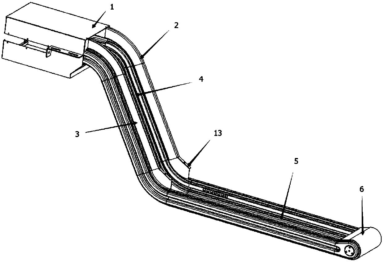
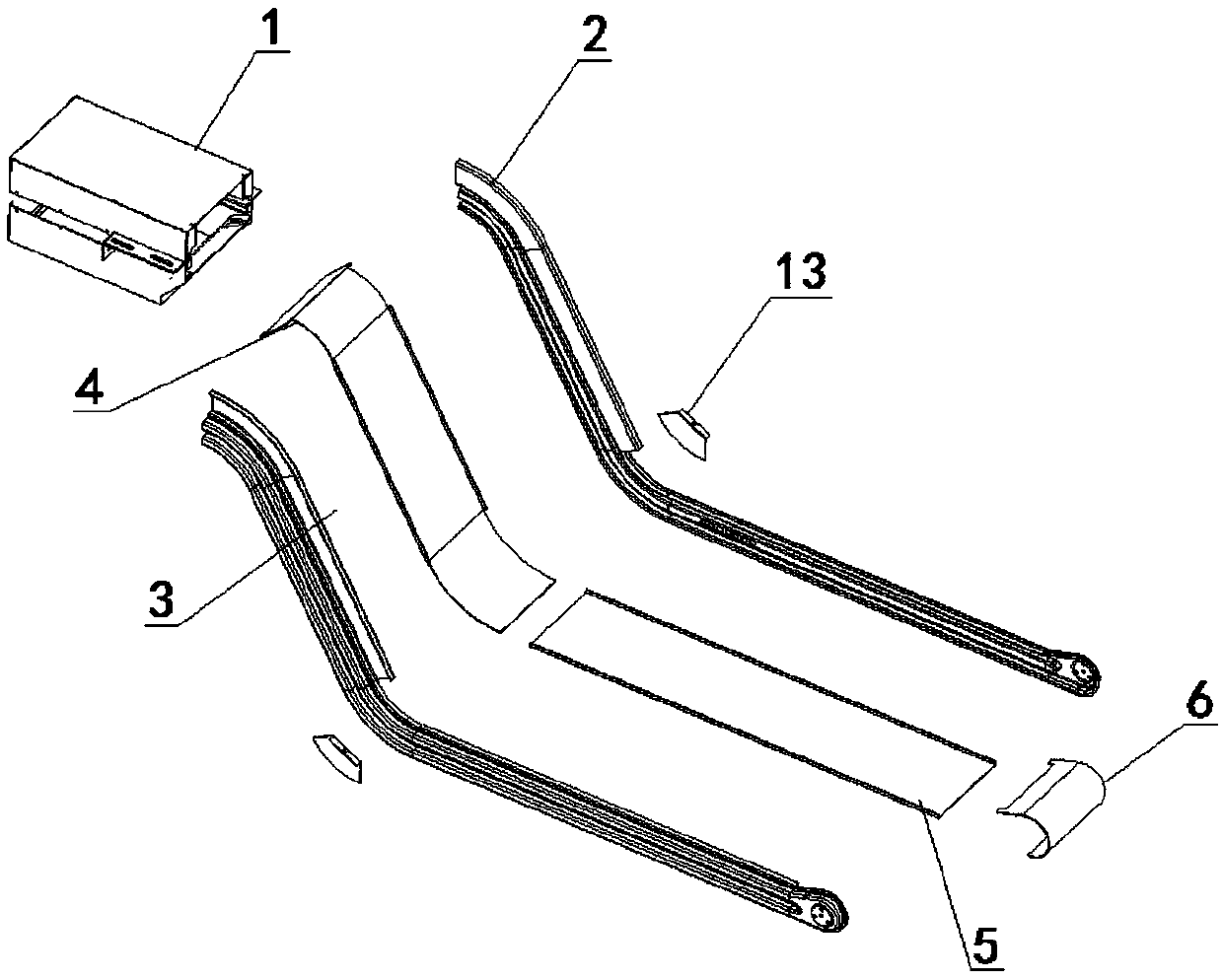
[0031] Example 1, as Figure 1-4 shown:

[0032] A chain plate chip conveyor structure includes a machine head module 1, a right side 2, a left side 3, a bottom sheet metal 4 of a lifting section, a bottom sheet metal 5 of a horizontal section, a tail arc sheet metal 6 and a side plate 13; The upper end of the bottom sheet metal 4 of the lifting section is welded to the head module 1, the lower end of the bottom sheet metal 4 of the lifting section is welded to the bottom sheet metal 5 of the horizontal section, and the lower end of the bottom sheet metal 5 of the horizontal section is welded to the tail arc sheet metal 6; The materials used for 3 and the right side 2 are "bow" type sheet metal materials. The left side 3 and the right side 2 are symmetrical in structure, and the left side 3 and the right side 2 are symmetrically welded to the bottom sheet metal 4 and the right side of the lifting section. Both sides of sheet metal 5 at the bottom of the horizontal segment;

...

Embodiment 2

[0042] Example 2, as Figure 4-5 shown:

[0043] Figure 4It is a cross-sectional view of the main body of the chip conveyor formed by one-time stamping. It can be seen that it consists of two horizontal section side plates 7 and one horizontal section bottom sheet metal 5. The number of parts is 3 and the number of welds is 2. Figure 5 It is a sectional view of the main body of the existing sheet metal bending process. The main body is composed of a shell 8, a right upper guide rail 9, a right lower guide rail 10, a left upper guide rail 11, and a left lower guide rail 12. The number of parts is 5 , the number of welds to be welded is 6. Therefore, the existing process needs to use a large number of parts and welds, which is not conducive to the rapid and efficient production and preparation of the chip conveyor and the guarantee of dimensional accuracy, and the accumulated deformation of the welding is relatively large.

Embodiment 3

[0044] Example 3, as Figure 1-4 shown:

[0045] A new structure and manufacturing process of chain plate chip conveyor, through standardized and modular design, the main body consists of machine head module 1, right side 2, left side 3, lifting section bottom sheet metal 4, horizontal section bottom sheet metal 5. The tail arc sheet metal 6 and the side plate 13 are composed.

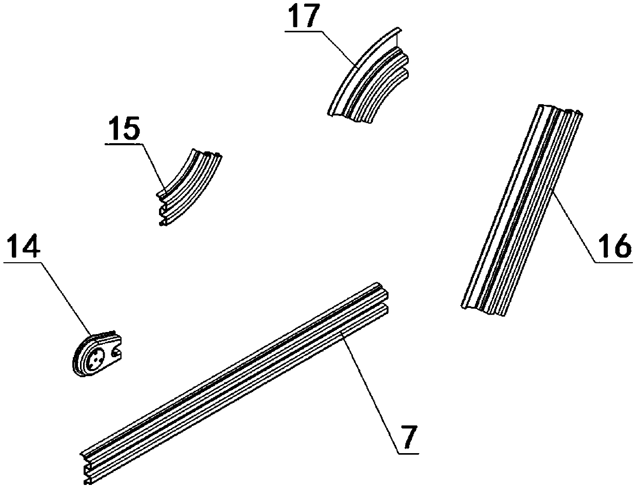
[0046] The manufacturing process mainly involves the one-step stamping and forming process of the following sheet metal parts: the right side 2 includes: the horizontal section side plate 7, the right tail side plate 14, the middle side plate 15, the lifting section side plate 16, and the head side plate 17. Among them, the parts included in the right side 2 are all a stamping forming process; the left side 3 and the side 2 are symmetrically designed, both of which are a one-time stamping and forming process.


PUM


Abstract

The invention relates to the technical field of machine tool manufacturing, in particular to a novel structure for a chain plate scrap removing device and a manufacturing technology of the novel structure. The novel structure for the chain plate scrap removing device comprises a machine head module, a right side, a left side, lifting section bottom sheet metal, horizontal section bottom sheet metal, tail arc sheet metal and a side plate. The machine head module is welded to the upper end of the lifting section bottom sheet metal. The horizontal section bottom sheet metal is welded to the lower end of the lifting section bottom sheet metal. The tail arc sheet metal is welded to the lower end of the horizontal section bottom sheet metal. The left side and the right side are made of bow-shaped sheet metal materials. Structures of the left side and the right side are symmetric, and the left side and the right side are symmetrically welded to the two sides of the lifting section bottom sheet metal and the two sides of the horizontal section bottom sheet metal. The novel structure for the chain plate scrap removing device is small in number of parts, convenient to manufacture and high in production efficiency and has good practical value.

Description

technical field [0001] The invention relates to the technical field of machine tool manufacturing, in particular to a chain plate chip conveyor structure. Background technique [0002] The machine tool industry continues to develop towards high-end and intelligent direction, and automatic chip removal equipment for machine tools has begun to be widely used. The chain plate chip conveyor is one of the most commonly used chip conveyors. However, the manufacturing cost of chip conveyors is very high. How to reduce the manufacturing cost of products and improve market competitiveness has become a problem that chip conveyor manufacturers have been exploring. [0003] At present, there are many patents on the chain plate chip conveyor and the specific parts of the chain plate chip conveyor. For example, the Chinese patent with the application number: 201620024338.5 discloses a chain plate chip conveyor, and its main claim is The working principle, structure, etc. are not related...

Claims


Application Information

Patent Timeline
Patent Type & Authority Patents(China)
IPC IPC(8): B23Q11/00B21D22/02
CPCB21D22/02B23Q11/0042
Inventor 马同堂赵敬
Owner 共享机床辅机(大连)有限公司
Why Eureka
Try Eureka