Aircraft landing dragging-type device

A tow-type, aircraft technology, applied in the field of aircraft landing tow-type devices, can solve the problems of low efficiency, long landing time, and extended landing distance, and achieve the effects of scientific and reasonable structure, reduced time, and safe and convenient use

Inactive Publication Date: 2017-11-24
韩丰收
View PDF5 Cites 2 Cited by
  • Summary
  • Abstract
  • Description
  • Claims
  • Application Information

AI Technical Summary

Problems solved by technology

[0003] The present invention provides a dragging device for aircraft landing, which can effectively solve the problem that the existing aircraft technical landing in the above-mentioned background technology is decelerated and landed through the deceleration parachute at the tail of the aircraft and the brakes of the aircraft hub, resulting in long landing time and long landing distance. Stretched, inefficient problem

Method used


Image

  • Aircraft landing dragging-type device

Examples


Embodiment

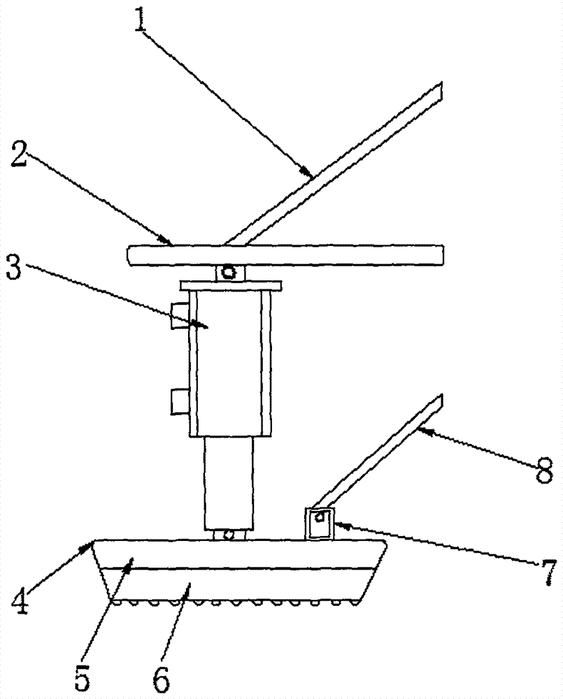
[0015] Example: such as figure 1 As shown, the present invention provides a kind of technical scheme, a kind of aircraft landing drag type device, comprises aircraft landing support bar 1, strut 2, hydraulic cylinder 3, drag plate 4, connecting column 7 and pull rod 8, one end of hydraulic cylinder 3 A strut 2 is connected, and the other end of the hydraulic cylinder 3 is connected with a drag plate 4, and the upper end of the strut 2 is connected with an aircraft landing support rod 1, and the drag plate 4 includes an upper support layer 5 and a lower support layer 6, and the upper support layer 5 The lower end of the lower branch layer 6 is provided, and the upper end of the upper branch layer 5 is provided with a connecting column 7 near the side of the hydraulic cylinder 3, and the upper end of the connecting column 7 is provided with a tie rod 8.

[0016] In order to increase the frictional force between the drag plate 4 and the ground, in this embodiment, preferably, the...


PUM


Abstract

The invention discloses an aircraft landing dragging-type device. The aircraft landing dragging-type device comprises an aircraft landing supporting rod, a connecting column and a pulling rod. One end of a hydraulic cylinder is connected with a supporting rod. The other end of the hydraulic cylinder is connected with a dragging plate. The upper end of the supporting rod is connected with the aircraft landing supporting rod. The dragging plate comprises an upper supporting layer and a lower supporting layer. The lower supporting layer is arranged at the lower end of the upper supporting layer. The pulling rod is arranged at the upper end of the connecting column. The aircraft landing dragging-type device is scientific and reasonable in structure and safe and convenient to use, an aircraft landing mode is improved, the hydraulic cylinder and the dragging plate are arranged, expansion and contraction of the dragging plate are controlled through the hydraulic cylinder, self weight of an aircraft body is transferred and decomposed through the dragging plate, the dragging plate is in friction with the ground (or with a deck), dragging and landing of an aircraft can be conducted, the time of aircraft landing can be shortened effectively, the distance of landing is shortened, the maintenance times are reduced, the design is simple in structure and convenient to operate and use, and meanwhile, the efficiency of aircraft landing is also improved.

Description

technical field [0001] The invention relates to the technical field of aircraft landing and pulling devices, in particular to an aircraft landing and pulling device. Background technique [0002] Aircraft refers to the forward thrust or pull generated by the power plant, and the lift generated by the fixed wings of the fuselage. It is a heavier-than-air aircraft flying in the atmosphere. It is a kind of fixed-wing aircraft and is also the most common one. , another fixed-wing aircraft is a glider, and the aircraft can be divided into jet aircraft and propeller aircraft according to the type of engine it uses. The existing aircraft technology landing is decelerated by the deceleration parachute at the tail of the aircraft and the brakes of the aircraft hub. , resulting in long landing time, long landing distance, and low efficiency. Contents of the invention [0003] The present invention provides a dragging device for aircraft landing, which can effectively solve the prob...

Claims


Application Information

Patent Timeline
IPC IPC(8): B64C25/42
CPCB64C25/42
Inventor 韩丰收
Owner 韩丰收
Why Eureka
Try Eureka