Efficient manufacturing method of insulated container and manufactured insulated container

A technology for a thermal insulation container and a manufacturing method, which is applied to thermal insulation containers, containers, household refrigeration devices, etc., can solve the problem of poor fusion and adhesion between glass glue and the main body of the container, the vacuum insulation container is not insulated, and the glass glue is easy to fall. and other problems, to achieve the effect of easy processing, ensuring thermal insulation effect and good fusion degree

Active Publication Date: 2017-11-24
FOSHAN KEITH TITANIUM TECH CO LTD
View PDF7 Cites 1 Cited by
  • Summary
  • Abstract
  • Description
  • Claims
  • Application Information

AI Technical Summary

Problems solved by technology

[0002] The existing tailless vacuum insulation container manufacturing method is to use glass glue to seal the cavity outside the container body at the bottom of the container body, and the container body needs to be packaged to suppress grooves and punch holes, and the production efficiency is low
And because the main body of the container is made of metal, while the glass glue is a non-metallic material, the degree of fusion and adhesion between the glass glue and the container body is not good, and the glass glue is easy to crack due to high temperature or vibration. The glue is easy to fall off, and the air enters the insulation cavity, causing the vacuum insulation container not to keep warm

Method used


Image

  • Efficient manufacturing method of insulated container and manufactured insulated container
  • Efficient manufacturing method of insulated container and manufactured insulated container
  • Efficient manufacturing method of insulated container and manufactured insulated container

Examples


Embodiment Construction

[0028] The technical solutions of the present invention will be further described below in conjunction with the accompanying drawings and through specific implementation methods.

[0029] The efficient method for manufacturing an insulated container of the present embodiment comprises the following steps:

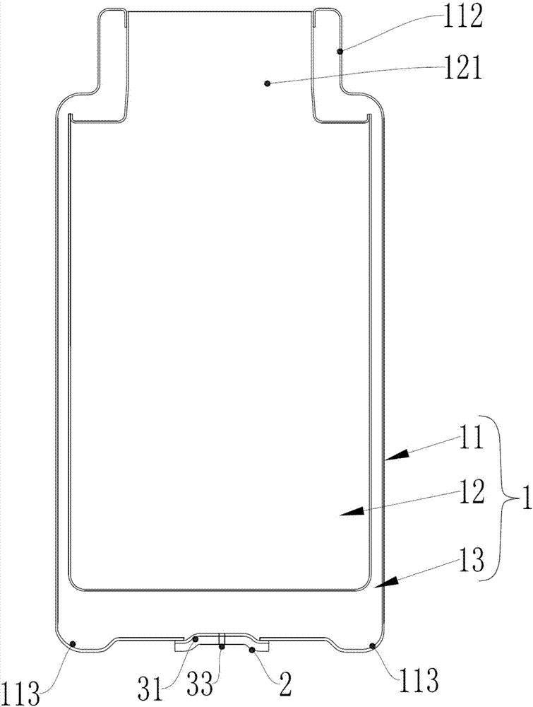
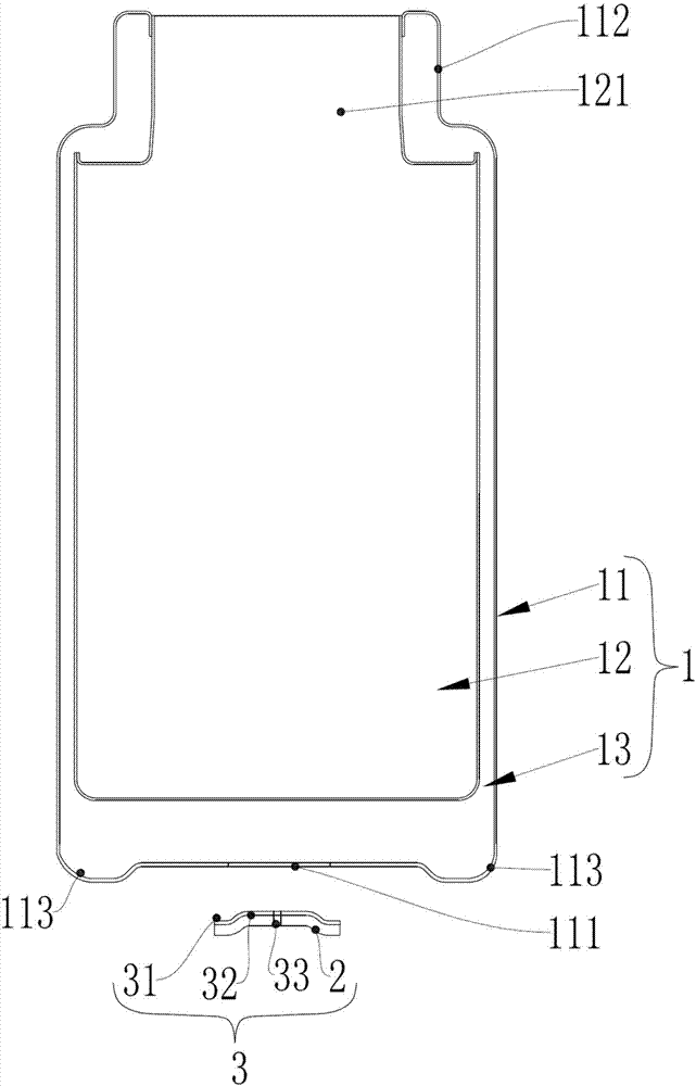
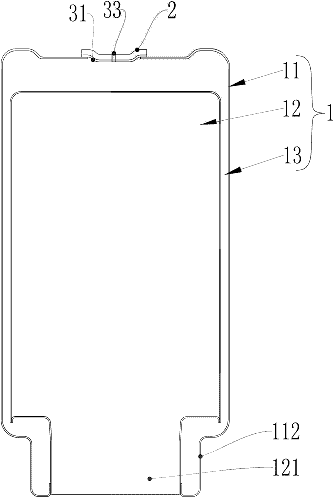
[0030] Step A, such as figure 1 , figure 2 As shown, the inner shell 12 is installed in the outer shell 11 to form the container main body 1, and the container main body 1 forms a thermal insulation cavity 13 between the outer shell 11 and the inner shell 12; meanwhile, the low-temperature sealing layer 2 and the substrate layer 31 welded to each other to form a sealing sheet 3;

[0031] Step B, such as figure 2 As shown, an exhaust groove 32 is provided on the sealing sheet 3, and an exhaust hole 33 is provided on the exhaust groove 32; at the same time, an installation hole 111 is provided on the bottom of the housing 11;

[0032] Step C, such as figure 1 As shown,...


PUM


Abstract

The invention discloses an efficient manufacturing method of an insulated container and the manufactured insulated container. The efficient manufacturing method comprises the following steps that A, an inner shell is mounted in an outer shell to form a container body, the container body forms an insulated cavity between the outer shell and the inner shell, and meanwhile a low-temperature sealing layer and a substrate layer are welded to each other to form a sealing piece; B, an exhaust groove is formed in the sealing piece, an exhaust hole is formed in the exhaust groove, and meanwhile an installing hole is formed in the bottom of the outer shell. The sealing piece and the bottom of the outer shell are welded to seal the installing hole, so that machining is more convenient, splicing of the container body and the preparation of the sealing piece are achieved synchronously, and the production efficiency is improved. The improvement cost of a production line is low. The low-temperature sealing layer and the substrate layer are both made of metal materials, so that compared with glass cement, the fusion degree is better; and the metal low-temperature sealing layer is not prone to breakage, and air can be effectively prevented from entering the insulated cavity through the exhaust hole.

Description

technical field [0001] The invention relates to the field of vacuum heat-retaining containers, in particular to an efficient method for manufacturing a heat-retaining container and a heat-retaining container manufactured therefor. Background technique [0002] The existing tailless vacuum insulation container manufacturing method is to use glass glue on the outside of the container body to seal the cavity at the bottom of the container body. Only when the container body is packaged can the grooves be pressed and holes punched, and the production efficiency is low. And because the main body of the container is made of metal, while the glass glue is a non-metallic material, the degree of fusion and adhesion between the glass glue and the container body is not good, and the glass glue is easy to crack due to high temperature or vibration. The glue is easy to fall off, and the air enters the insulation cavity, causing the vacuum insulation container not to keep warm. Contents ...

Claims


Application Information

Patent Timeline
Patent Type & Authority Applications(China)
IPC IPC(8): B65D81/38
CPCB65D81/3841
Inventor 刘敏业
Owner FOSHAN KEITH TITANIUM TECH CO LTD
Why Eureka
Try Eureka