
Combustion system and method for boiler at front wall or rear wall of power station

A technology of combustion system and front wall, which is applied in the direction of combustion method, combustion with multiple fuels, combustion with block fuel and liquid fuel, etc., can solve the problems of poor combustion stability and high emission, and achieve low economic benefits, Reduce floor space and help to ignite in time

Active Publication Date: 2021-06-04
HARBIN INST OF TECH
View PDF9 Cites 0 Cited by
  • Summary
  • Abstract
  • Description
  • Claims
  • Application Information

AI Technical Summary

Problems solved by technology

[0005] The present invention provides a combustion system and method for boilers on the front wall or rear wall of a power station to solve the problems of low-load and ultra-low-load stable combustion capability, NO x The problem of high emissions

Method used


Image

  • Combustion system and method for boiler at front wall or rear wall of power station
  • Combustion system and method for boiler at front wall or rear wall of power station
  • Combustion system and method for boiler at front wall or rear wall of power station

Examples


Embodiment Construction

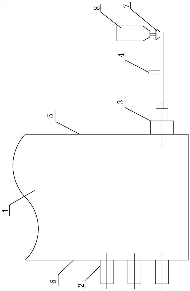
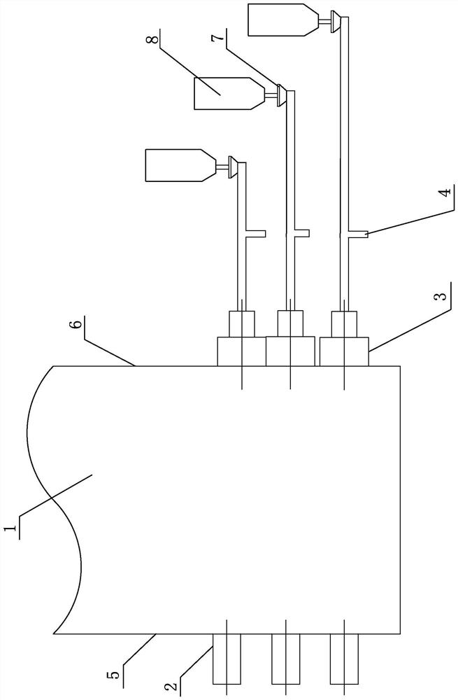
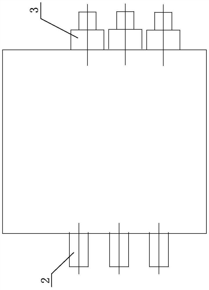
[0026] see Figure 1-Figure 3 As shown, 1. A combustion system of a boiler on the front wall or rear wall of a power station in this embodiment is characterized in that it includes a furnace 1, a main burner 2, a pre-chamber burner 3, a powder feeder 7 and a powder storage bin 8 , the front wall 5 and the rear wall 6 are arranged on the furnace wall of the furnace 1, wherein the pre-combustion chamber burner 3 is connected to the powder feeder 7, the powder storage bin 8 is connected to the powder feeder 7, and the main burner 2 is arranged on the rear wall 6 or the front wall. wall 5, the pre-combustion chamber burner 3 is arranged on the front wall 5 or the rear wall 6, and the boiler is a wall-type boiler. The main burner 2 is arranged correspondingly to the pre-chamber burner. When the main burner is arranged on the rear wall 6, the pre-chamber burner 3 is arranged on the front wall 5, and vice versa. The boiler operates the pre-combustion chamber burner under low load an...


PUM


Abstract

The invention discloses a combustion system and method for a boiler at a front wall or a rear wall of a power station. The combustion system comprises a furnace chamber, a primary combustor, a pre-combustion chamber combustor, a powder feeder and a powder storage bin, wherein the pre-combustion chamber combustor is connected to the powder feeder; and the pre-combustion chamber combustor is arranged at the front wall or the rear wall. The method comprises the following steps: switching off the pre-combustion chamber combustors one by one after the furnace hearth flue temperature reaches a given value, gradually switching on the main combustor to introduce pulverized coal, closing air valves of the pre-combustion chamber combustors, and opening a circulating flue gas valve; when the boiler is in full-load operation, making all pre-combustion chamber combustors in an off-state, and opening the circulating flue gas valve; when the boiler is in ultralow-load operation, not introducing pulverized coal to the primary combustor, and opening the main combustor air valve; after ultralow-load operation is ended, stopping the pre-combustion chamber combustors one by one, and operating the main combustors one by one, and introducing circulating flue gas into the pre-combustion chamber combustor. The combustion system solves the problems that a pulverized coal boiler of the power station is poor in low-load and ultralow-load stable combustion ability and is high in NOx emission amount.

Description

technical field [0001] The invention relates to a pulverized coal boiler of a power station, in particular to a combustion system and method for the boiler on the front wall or back wall of the power station, which is suitable for the flexible transformation of the pulverized coal boiler of the power station. Background technique [0002] In recent years, the installed capacity of clean energy has increased year by year, but it has the characteristics of intermittent, seasonal, fluctuating, and low reactive power supply performance, which poses a challenge to the peak-shaving capability of thermal power units. In order to flexibly adapt to power demand, pulverized coal boilers often need to operate under ultra-low load or low load. Therefore, ensuring the stable operation of the boiler under ultra-low load or low load is an urgent problem to be solved in the operation of pulverized coal boilers in power plants. [0003] NO x is the main factor for the formation of smog, NO...

Claims


Application Information

Patent Timeline
Patent Type & Authority Applications(China)
IPC IPC(8): F23C5/08F23K3/02F23L1/00F23L9/00
CPCF23C5/08F23K3/02F23L1/00F23L9/00F23K2203/201
Inventor 陈智超乔彦宇关硕曾令艳李争起
Owner HARBIN INST OF TECH
Learn More