Combustion system and application method for lower layer of counter-combustion boiler

A combustion system and counter-combustion technology, which is applied in the direction of combustion methods, combustion using lump fuel and powder fuel, combustion using lump fuel and gaseous fuel, etc., and can solve the problems of poor combustion stability at low loads and high emissions , to achieve the effect of increasing the stable operating load range, reducing NOx emissions, and reducing NOx emissions

Active Publication Date: 2021-12-03
HARBIN INST OF TECH
View PDF16 Cites 0 Cited by
  • Summary
  • Abstract
  • Description
  • Claims
  • Application Information

AI Technical Summary

Problems solved by technology

[0006] The purpose of the invention is to solve the problem of poor low-load stable combustion capability and NO x High emissions and other issues, and then provide a combustion system and use method for the lower layer of the counter-fired boiler;

Method used


Image

  • Combustion system and application method for lower layer of counter-combustion boiler
  • Combustion system and application method for lower layer of counter-combustion boiler
  • Combustion system and application method for lower layer of counter-combustion boiler

Examples


specific Embodiment approach 1

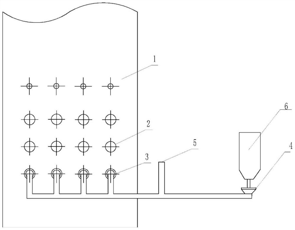
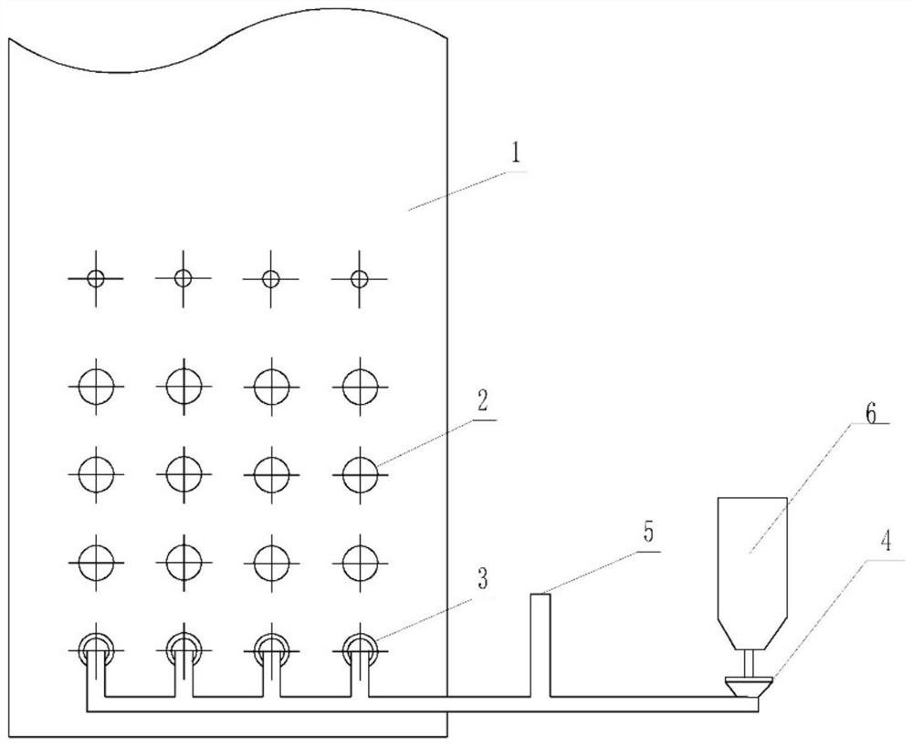
[0025] Specific implementation mode one: refer to Figure 1 to Figure 3 This embodiment is described. This embodiment provides a combustion system for the lower layer of the opposed combustion boiler. The combustion system includes a main burner 2, a pre-chamber burner 3, a powder feeder 4 and a powder storage bin 6. The main The burner 2 is arranged inside the furnace 1, the pre-chamber burner 3 is arranged under the main burner 2, the feed end of the pre-chamber burner 3 is connected with the discharge end of the powder feeder 4 through a pipeline, and the powder storage bin 6 Inverted at the feeding end of the powder feeder 4, and the powder storage bin 6 is disconnected from the powder feeder 4;

[0026]In this embodiment, by connecting the pre-chamber burner 3 with the powder feeder 4, the high-concentration powder feeding of the powder feeder 4 to the pre-chamber burner 3 can be realized, and the pre-chamber burner 3 and the main burner 2 have Two arrangements, the firs...

specific Embodiment approach 2

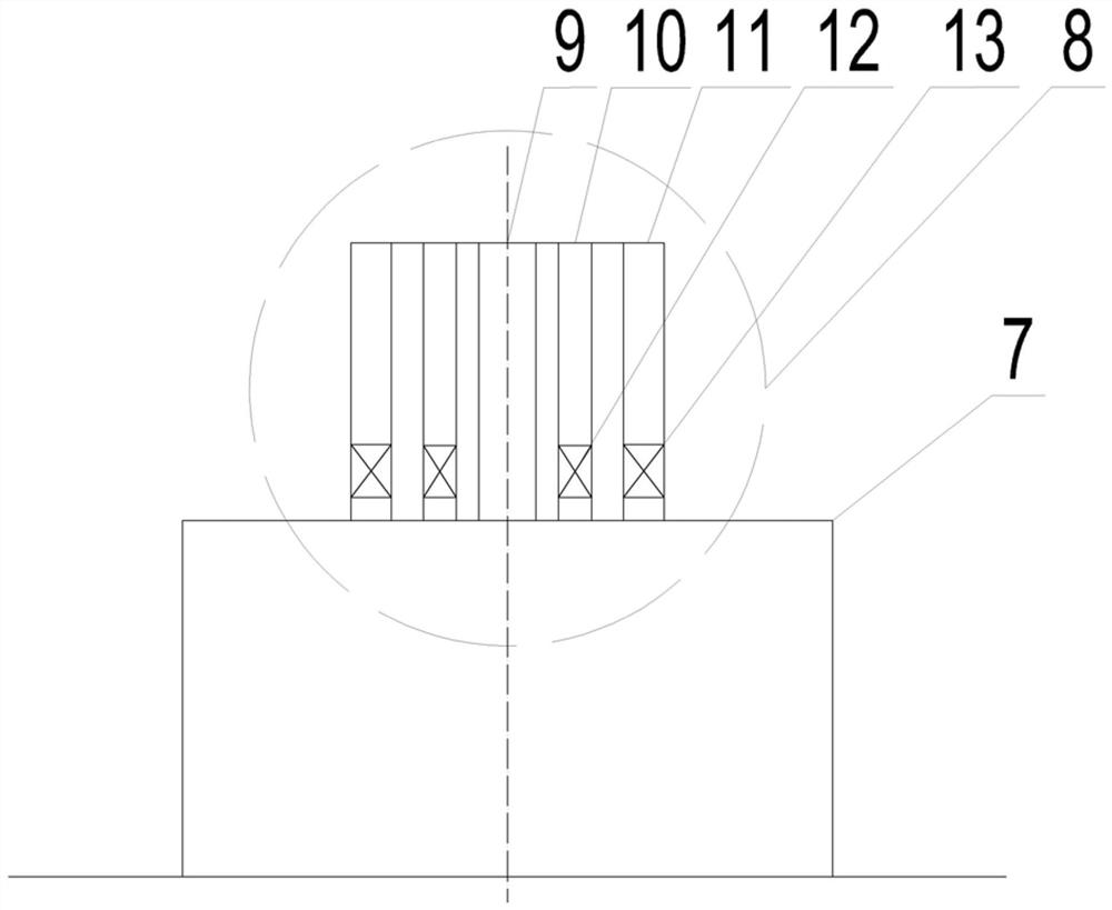
[0027] Specific implementation mode two: refer to Figure 1 to Figure 3 Describe this embodiment, this embodiment is to further limit the pre-chamber burner 3 described in the first specific embodiment, in this embodiment, the pre-chamber burner 3 includes a pre-chamber 7 and a swirl burner 8. The pre-combustion chamber 7 is set under the main burner 2 or at the bottom of the main burner 2, the swirl burner 8 is set in the pre-combustion chamber 7, and the feed end of the swirl burner 8 passes through The pipeline is connected to the discharge end of the powder feeder 4 . Other compositions and connection methods are the same as those in Embodiment 1.

specific Embodiment approach 3

[0028] Specific implementation mode three: refer to Figure 1 to Figure 3 Describe this embodiment, this embodiment is to further limit the swirl burner 8 described in the second specific embodiment, in this embodiment, the swirl burner 8 includes a plurality of feed ports, the swirl burner 8 Connect to the discharge end of the powder feeder 4 through a shunt pipe, the shunt pipe includes a plurality of feed outlets and a feed inlet, and each outlet of the shunt pipe communicates with a feed inlet of the swirl burner 8 , the feed port of the shunt pipe is connected to the discharge end of the powder feeder 4, and other components and connection methods are the same as those in the second embodiment.

[0029] Such arrangement is beneficial to improve the working efficiency of the pre-chamber burner 3 in order to ensure that the powder feeding machine 4 feeds the pre-chamber burner 3 high-concentration powder more evenly.


PUM


Abstract

A combustion system for the lower layer of a counter-combustion boiler and a use method thereof relate to the technical field of boiler combustion in power plants. The invention aims to solve the problem of difficulty in stable combustion under ultra-low load existing in the existing power plant boilers. The pre-chamber burner consists of a swirl burner and a pre-chamber. Arrange a layer of pre-chamber burners under the main burner or replace the original burners on the bottom layer of the hedge boiler used in the power station with pre-chamber burners, and the pre-chamber burners are connected to the powder feeder separately to achieve high concentration Give powder without changing the main burners on the upper and middle floors. Under ultra-low load or low load conditions, turning off the main burner and running the pre-chamber burner can stabilize the boiler. The pre-combustion chamber burner is arranged with a recirculation flue gas pipeline. When the pre-combustion chamber burner is out of operation, the recirculation flue gas or air is introduced to prevent the pre-combustion chamber burner from burning. The pre-combustion chamber burner is running, and the main burner is fed with air when it is out of service to prevent it from being burned.

Description

technical field [0001] The invention relates to the technical field of power plant boiler combustion, in particular to a combustion system and a use method for the lower layer of a counter-combustion boiler. Background technique [0002] With the large-scale grid integration of new energy sources such as wind power and solar power, the power grid needs thermal power units to provide flexible peak-shaving capabilities. In order to absorb more new energy, thermal power units need to provide a wider load regulation range, especially in low-load operating conditions for a long time. The primary problem in the low-load operation of thermal power units is to ensure the stability of combustion under ultra-low load or low load conditions. Therefore, ensuring the stable operation of the boiler under ultra-low load or low load is an urgent problem to be solved in the operation of power plant boilers. [0003] Prechamber burners can greatly improve the above problems. Since the pre-...

Claims


Application Information

Patent Timeline
Patent Type & Authority Patents(China)
IPC IPC(8): F23C5/08F23L1/00F23L9/00
CPCF23C5/08F23L1/00F23L9/00
Inventor 陈智超乔彦宇关硕曾令艳李争起
Owner HARBIN INST OF TECH
Why Eureka
Try Eureka