Combustor

A technology for burners and controllers, which is applied in the direction of burners, combustion methods, and controlled combustion. It can solve problems such as high cost and failure to achieve fuel flexibility, and achieve increased load range, fuel flexibility, and low-load stability. burning effect

Pending Publication Date: 2019-03-05
HEPU TECH DEV BEIJING CO LTD
View PDF8 Cites 2 Cited by
  • Summary
  • Abstract
  • Description
  • Claims
  • Application Information

AI Technical Summary

Problems solved by technology

[0004] The technical solutions of the prior art generally require large-scale and high-cost modification of the boiler body and the heating surface of the boiler, and generally only one fuel is allowed to burn after the modification. For example, a pulverized coal boiler is completely changed to a biomass-fired boiler. Fuel flexibility is not actually achieved

Method used


Image

  • Combustor
  • Combustor
  • Combustor

Examples


Embodiment 1

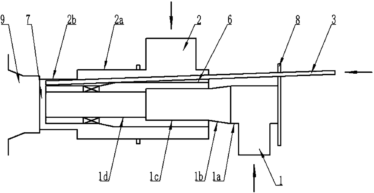
[0029] figure 1 It is a schematic diagram of the internal structure of the connection between the burner and the furnace provided by Embodiment 1 of the present invention.

[0030] Please refer to figure 1 , the burner includes: a burner outlet 7, a primary air channel 1, a secondary air channel 2, and an oil and gas supply gun 3.

[0031] The burner outlet 7, which contains one or more fuel outlets, is used to connect to the furnace 9 of the boiler, so as to deliver one or more fuels into the furnace 9 for combustion. Specifically, the burner outlet 7 is composed of one or more fuel outlets to form a unified outlet for flexible connection with the furnace 9, where the furnace 9 refers to the furnace of a large power plant pulverized coal boiler.

[0032] The side wall of the primary air channel 1 is provided with a primary air inlet, and the other end extends to the burner outlet 7 and is formed as a primary air outlet. Primary air channel 1 is used to convey the mixture o...

Embodiment 2

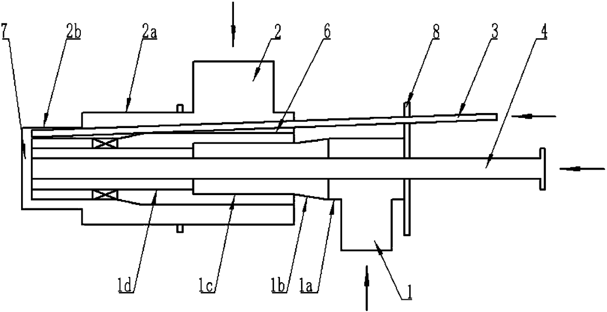
[0057] figure 2 It is a schematic diagram of the internal structure of the burner provided by Embodiment 2 of the present invention.

[0058] Please refer to figure 2 , on the basis of the first embodiment, the burner of this embodiment adds a biomass powder supply gun 4, one end of which is formed as a powder inlet, and the other end extends to the burner outlet 7 and is formed as a powder outlet for conveying biomass powdered fuel. The biomass powder in the biomass powder supply gun 4 enters the furnace 9 for combustion under the air of the primary wind speed in the primary air channel 1, so that traditional large-scale thermal power plants can burn a large amount of renewable energy such as biomass powder fuel.

[0059] Optionally, the biomass powder supply gun 4 is arranged at the center of the primary air channel 1 , that is, the axis of the biomass powder supply gun 4 coincides with the axis of the primary air channel 1 .

[0060] Optionally, the cross section of th...

Embodiment 3

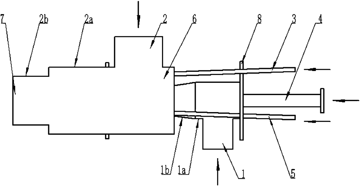
[0067] The difference between the burner of this embodiment and the second embodiment is that the installation position of the biomass powder supply gun 4 is different. In this embodiment, the axis of the biomass powder supply gun 4 and the axis of the primary air channel 1 form a second angle.

[0068] Optionally, the angle range of the second included angle is 0°-30°.

[0069] The structure and connection relationship of other components of the burner in this embodiment are the same as those in Embodiment 2, and will not be repeated here.


PUM


Abstract

The invention discloses a combustor, and belongs to the technical field of fuel combustion equipment. The combustor comprises a combustor outlet (7), a primary air channel (1), a secondary air channel(2) and an oil-gas supply gun (3). The combustor outlet (7) comprises an outlet for one or more kinds of fuel and is used for being connected to a hearth (9) of a boiler so as to convey one or more kinds of fuel into the hearth (9) to be combusted. A primary air inlet is formed in the side wall of one end of the primary air channel (1), and the other end of the primary air channel (1) extends tothe combustor outlet (7) so as to form a primary air outlet. A secondary air inlet is formed in the side wall of one end of the secondary air channel (2), and the other end of the secondary air channel (2) extends to the combustor outlet (7) so as to form a secondary air outlet. An oil-gas inlet is formed in one end of the oil-gas supply gun (3), the other end of the oil-gas supply gun (3) extendsto the combustor outlet (7) so as to form an oil-gas outlet, and the oil-gas supply gun (3) is used for conveying liquid or gas fuel in a time sharing manner. According to the combustor, the oil-gassupply gun (3) is additionally mounted, and therefore multiple kinds of fuel can be supplied and combusted on the basis of primary air and secondary air of a traditional pulverized coal boiler combustor.

Description

technical field [0001] The invention relates to the technical field of fuel combustion equipment, in particular to a burner. Background technique [0002] Due to global warming and the response to climate change, there is a need to reduce the carbon emission intensity of coal-fired thermal power units. Therefore, coal-fired power plants need to purchase green certificates or carbon indicators to maintain annual power generation load, or they need to undergo fuel flexibility transformation to become thermal power plants with low carbon emission intensity. [0003] Most of the boilers of existing large-scale thermal power units are in the form of high-efficiency pulverized coal boilers. In order to solve the above problems, the existing technology has carried out fuel flexibility transformation, but these solutions themselves have the following defects: [0004] The technical solutions of the prior art generally require large-scale and high-cost modification of the boiler bod...

Claims


Application Information

Patent Timeline
Patent Type & Authority Applications(China)
IPC IPC(8): F23D17/00F23N1/02F23L9/00
CPCF23D17/00F23L9/00F23N1/022
Inventor 杨豫森崔华徐波谭智陈辉展望陈超朱明志
Owner HEPU TECH DEV BEIJING CO LTD
Why Eureka
Try Eureka