Rotary Damper

a damper and rotary technology, applied in the direction of liquid based dampers, shock absorbers, mechanical instruments, etc., can solve the problems of small load range to be coped, valve body abrupt deformation, fluid passage closure, etc., to reduce braking force, enhance yield, and increase load cope

Active Publication Date: 2011-01-20
SOMIC MANAGEMENT HLDG INC
View PDF31 Cites 2 Cited by
  • Summary
  • Abstract
  • Description
  • Claims
  • Application Information

AI Technical Summary

Benefits of technology

[0017]According to the invention described in the item 1, it is possible to enlarge the range of load to be coped, and to exhibit a braking force which appropriately corresponds to variation in load. Even when the rotary dampers are mass-produced, since it is possible to employ, as valve mechanisms, valve bodies whose shape and size can easily be worked precisely, yields can be enhanced.
[0018]According to the invention described in the items 2 and 3, the same effect as that of the invention of the item 1 can be obtained.
[0019]According to the invention described in the item 4, even when the load is varied, when the load is less than the predetermined value, the braking force can be reduced and when the load is equal to or higher than the predetermined value, the braking force can be increased.
[0020]According to the invention described in the item 5, when fluid reversely flows in the operating chamber, the braking force can be reduced to an extremely small value.
[0021]According to the invention described in the item 6, it is possible to reduce the outer diameter of the casing without reducing the rotation angle of the pushing member.
[0022]According to the invention described in the item 7, the same effect as that described in the item 1 can be obtained.

Problems solved by technology

According to the valve body, however, since a straight distance between an opening of the fluid passage closed with the valve body and the other surface of the valve body opposed to the opening is short, there is a problem that the load range which is to be coped is small.
If the load reaches a given value, there is also a problem that the valve body is abruptly deformed and the fluid passage is closed.
Further, since the valve body is bent, if the valve bodies are mass-produced, it is not easy to form the valve bodies into uniform shape, and there is a problem that a slight error in shape results in great influence on braking characteristics.
When an outer diameter of a casing is large, it is easy to secure the width of the vane or the like on which the valve body can be disposed, but in this case, there is a problem that the installation space of the rotary damper is inevitably increased.
On the other hand, to reduce the installation space of the rotary damper, if the outer diameter of the casing is reduced, the width of the vane or the like is reduced to secure the rotation angle of the vane or the like, and there is a problem that it becomes difficult to provide the valve body.

Method used


Image

  • Rotary Damper
  • Rotary Damper
  • Rotary Damper

Examples


first embodiment

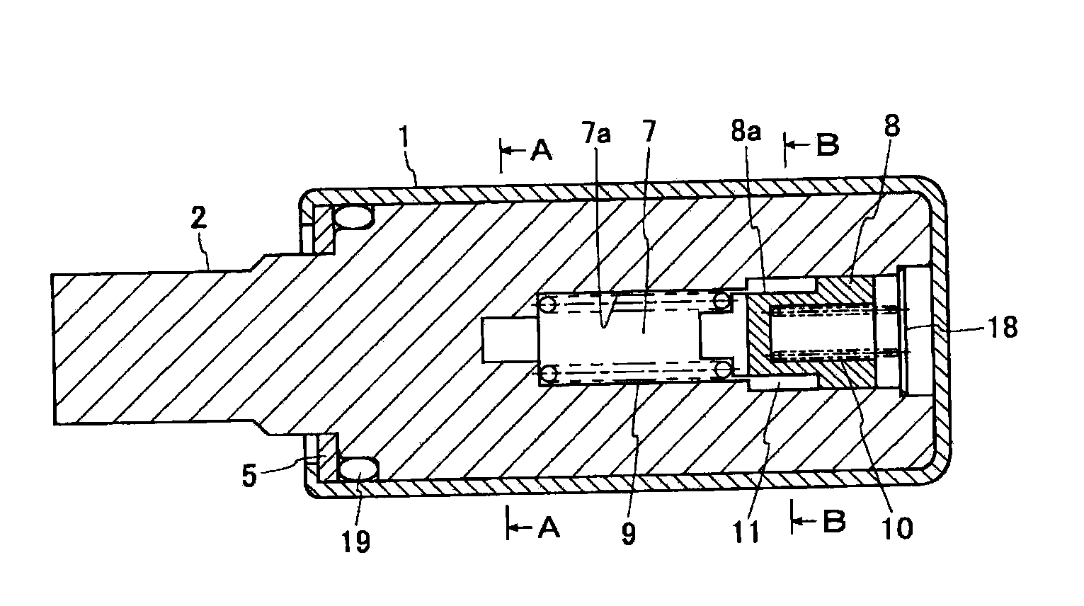
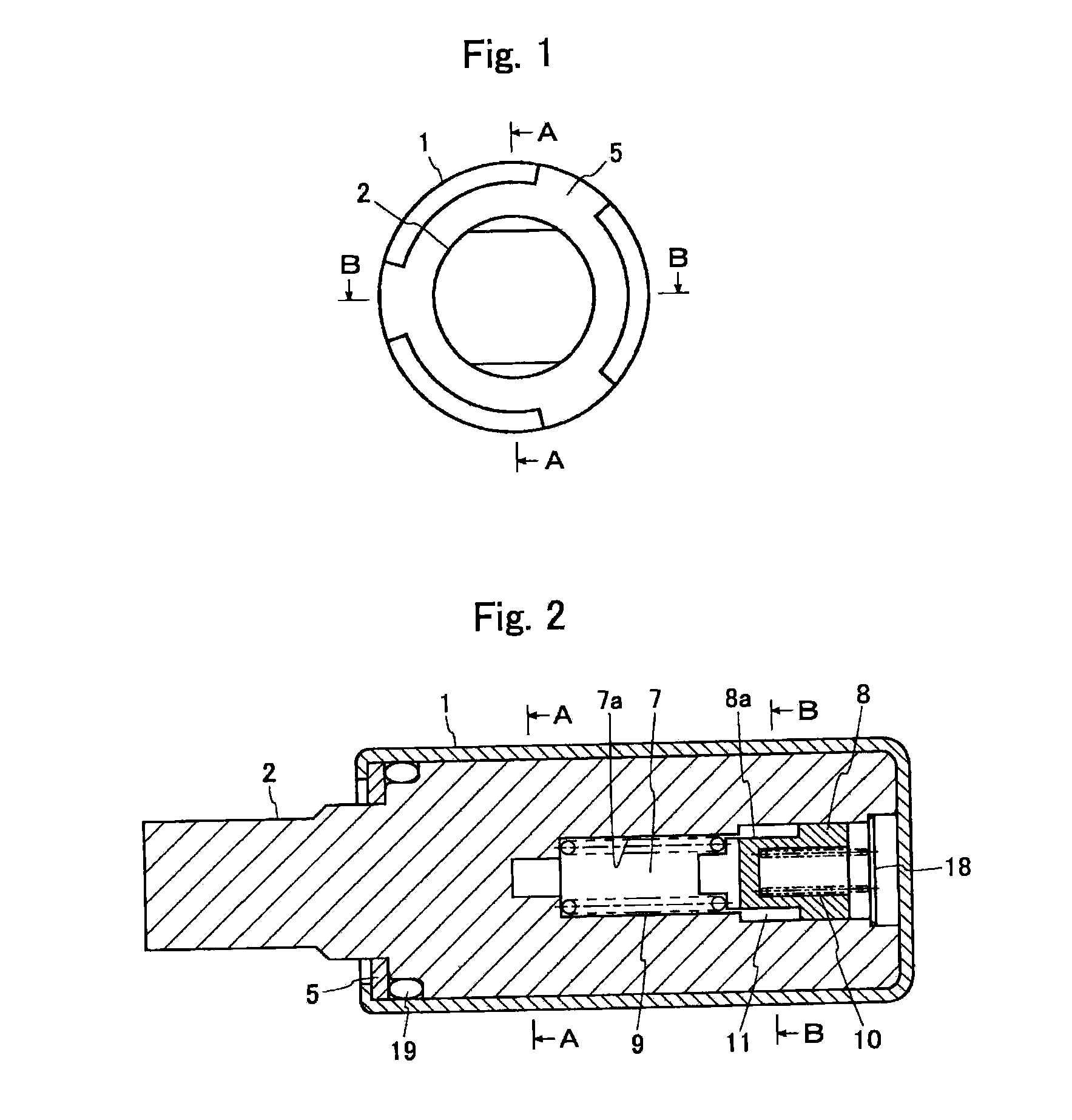
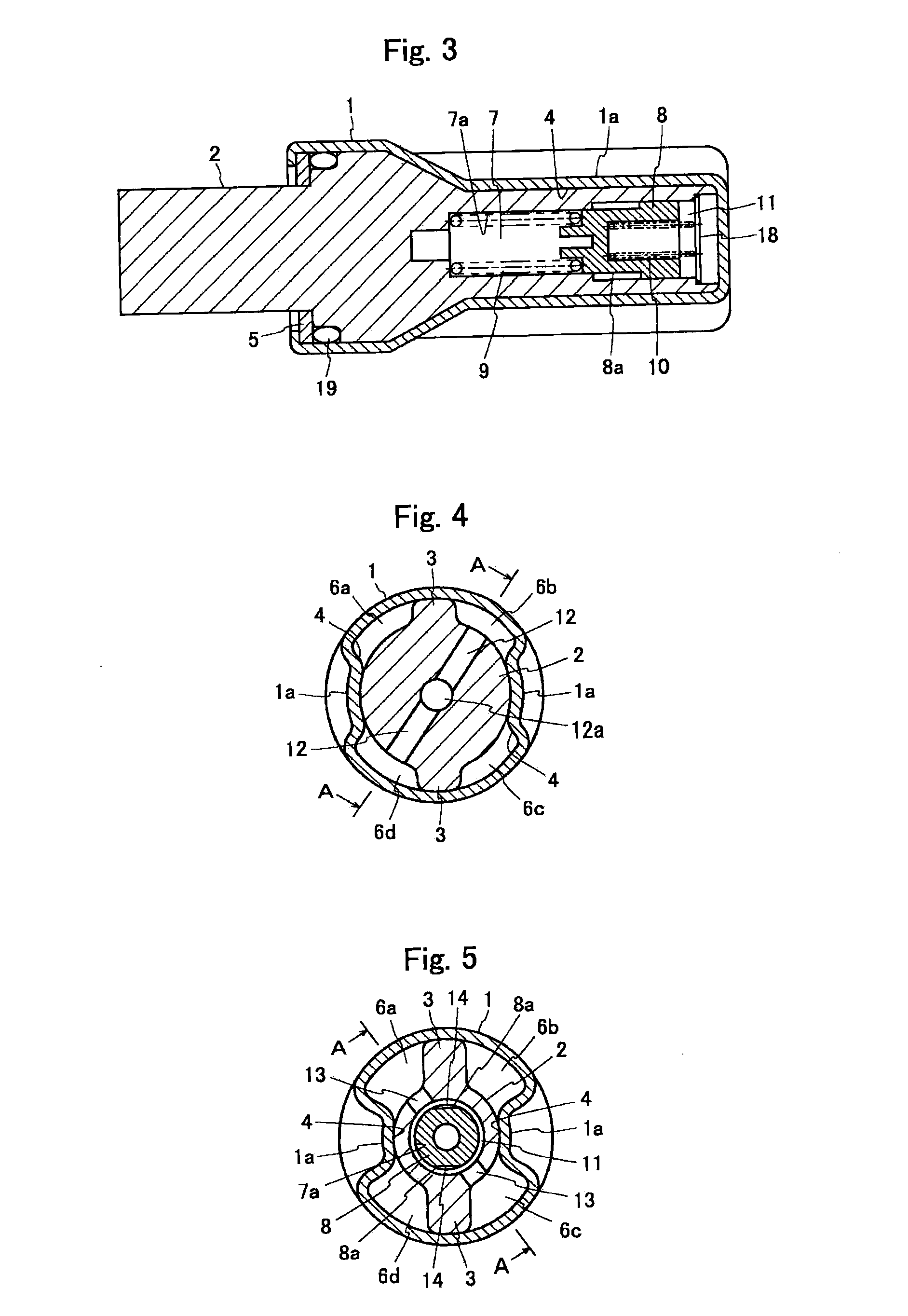
[0116]FIGS. 1 to 7 show a rotary damper according to a first embodiment of the present invention. As shown in these drawings, the rotary damper of the embodiment includes a casing 1, a shaft 2, vanes 3, division walls 4 and a valve mechanism.

[0117]The casing 1 is hollow, one end thereof is opened and the other end is closed. The opening of the casing 1 is closed with a lid 5. The lid 5 is mounted by crimping an end of the casing 1. The casing 1 includes division walls 4 which divide a space formed between the casing 1 and the shaft 2. The casing 1 and the division walls 4 are integrally formed by press working. Recesses 1a are formed in division wall forming sections. The recess 1a functions as the coupling section (see FIGS. 3 to 5). Viscous fluid such as silicon oil is charged into the casing 1.

[0118]The shaft 2 is provided in the casing 1 such that the shaft 2 can rotate relative to the casing 1. The shaft 2 is integrally formed with the vanes 3. Four chambers 6a to 6d (a first c...

second embodiment

[0135]A rotary damper of a second embodiment is different from the rotary damper of the first embodiment in the shape of the valve body 8. That is, the valve body 8 of the second embodiment is provides at its outer periphery with a tapered surface 8b as shown in FIGS. 14 and 15.

[0136]FIG. 14 shows a state before the valve body 8 forwardly moves in the operating chamber 7. FIG. 15 shows a state after the valve body 8 forwardly moves in the operating chamber 7. As shown in these drawings, according to the valve mechanism having such a valve body 8, as the moving distance of the valve body 8 which forwardly moves in the operating chamber 7 is increased, the area of the flow path 14 formed between the wall surface of the peripheral wall 7a of the operating chamber 7 and the tapered surface 8b formed on the valve body 8 is reduced. With this, the reducing amount can be increased. Thus, the second embodiment can also exhibit the same effect as that of the first embodiment.

third embodiment

[0137]In a rotary damper of a third embodiment, the shape of the valve body 8 is different from that of the rotary damper of the first embodiment. That is, the valve body 8 of the third embodiment is provided at its outer periphery with a substantially V-shaped groove 8c as shown in FIG. 16.

[0138]According to the valve mechanism having such a valve body 8, as the moving distance of the valve body 8 which forwardly moves in the operating chamber 7 is increased, the area of the flow path 14 formed between the wall surface of the peripheral wall 7a of the operating chamber 7 and the groove 8c formed in the valve body 8 is reduced. With this, the reducing amount can be increased. Thus, the third embodiment can also exhibit the same effect as that of the first embodiment.


PUM


Abstract

The present invention provides a rotary damper in which both yields and braking characteristics can be enhanced. The rotary damper of the invention includes a valve mechanism which comprises an operating chamber 7 through which fluid can pass, a valve body 8 which forwardly moves from a natural state position when the valve body 8 receives fluid pressure and which can forwardly moves in the operating chamber 7, and a first spring 9 capable of giving a resistance to the forward movement of the valve body 8. The valve mechanism can reduce a flow rate of fluid which passes through the operating chamber 7 by a flow path 14 formed between the valve body 8 and a peripheral wall 7a of the operating chamber 7. A reducing amount of fluid can be increased as a moving distance of the valve body 8 which forwardly moves in the operating chamber 7 is increased.

Description

TECHNICAL FIELD[0001]The present invention relates to a rotary damper capable of changing a braking force in accordance with variation in load, and to a product having the rotary damper.BACKGROUND ART[0002]Japanese Patent Application Laid-open No. 2004-3584 discloses a rotary damper in which a valve body comprising a leaf spring is disposed on a vane or a division wall (hereinafter called “vane or the like”), and a flow rate of viscous fluid passing through a fluid passage can be adjusted in accordance with variation in load by the valve body (see paragraphs 0042 to 0053 and FIGS. 7 to 11 of this publication).[0003]One surface of the valve body of the rotary damper is deflected such as to project, the one surface receives fluid pressure and is deformed, and a size of a flow path through which fluid passes can be changed. According to the rotary damper, since the flow rate of fluid passing through the fluid passage can be limited in accordance with a load by the valve body, it is pos...

Claims


Application Information

Patent Timeline
Patent Type & Authority Applications(United States)
IPC IPC(8): F16F9/12F16F9/14
CPCF16F9/14
Inventor KANNO, HIDENORISHIMURA, RYOTAITAGAKI, MASANORI
Owner SOMIC MANAGEMENT HLDG INC
Why Eureka
Try Eureka