Reinforced panel

a technology of reinforced panels and panels, applied in the direction of wing adjustments, aircraft floors, weighing apparatuses, etc., can solve the problems of reducing the understanding of failure mechanisms and their behaviour, not widely accepted compositions in primary structures, and widespread lack of knowledge and know-how

a technology of reinforced panels and panels, applied in the direction of wing adjustments, aircraft floors, weighing apparatuses, etc., can solve the problems of reducing the understanding of failure mechanisms and their behaviour, not widely accepted compositions in primary structures, and widespread lack of knowledge and know-how

US8302486B2Inactive Publication Date: 2012-11-06AIRBUS OPERATIONS LTD

Image

  • Reinforced panel
  • Reinforced panel
  • Reinforced panel

Examples


Embodiment Construction

)

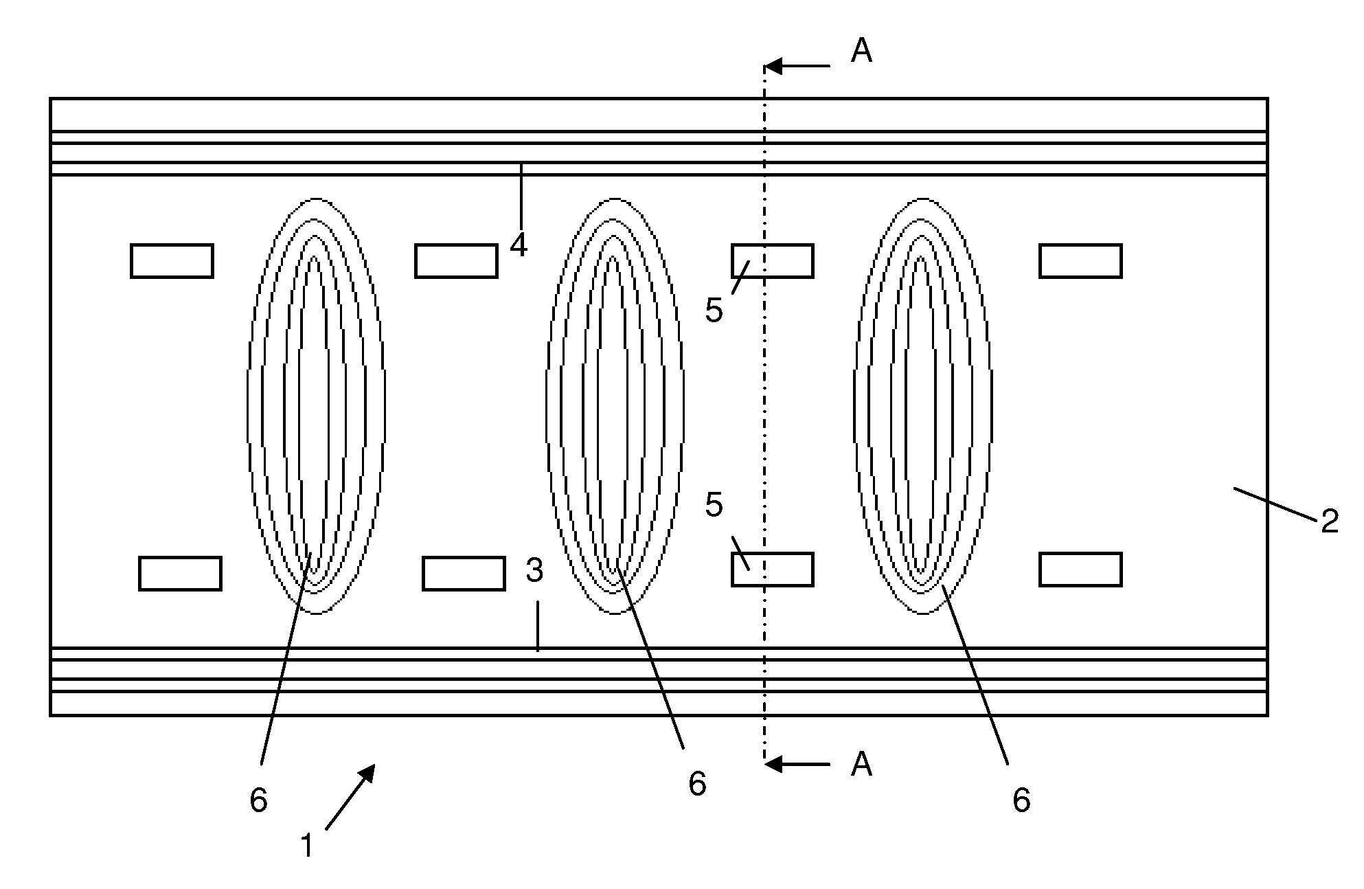
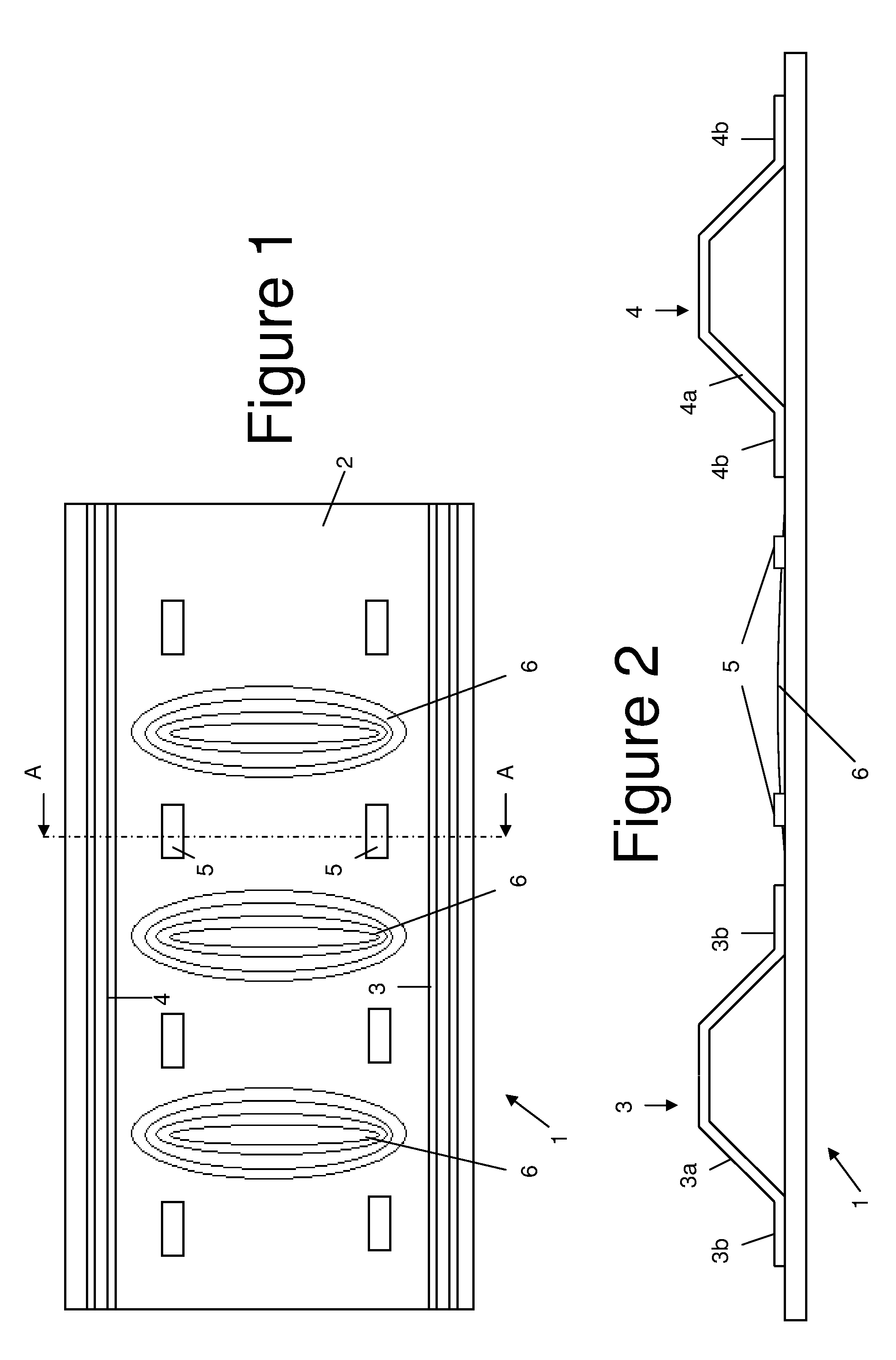
[0031]A portion of a reinforced panel 1 is shown in FIGS. 1 and 2. The panel may form, for example, the skin of an aircraft wing or fuselage. The panel comprises a composite skin 2; a plurality of composite stringers 3,4 co-cured to the skin; and a two-dimensional array of piezoelectric strain actuators 5 positioned between the stringers. In the case of an aircraft wing, the stringers run in a span-wise direction from the root of the wing towards its tip.

[0032]FIG. 1 shows only a small portion of the panel, which extends further in both the horizontal and vertical directions. As shown in FIG. 2, each stringer comprises a web 3a,4a extending from the skin and a pair of flanges3b,4b which are bonded to the skin 2.

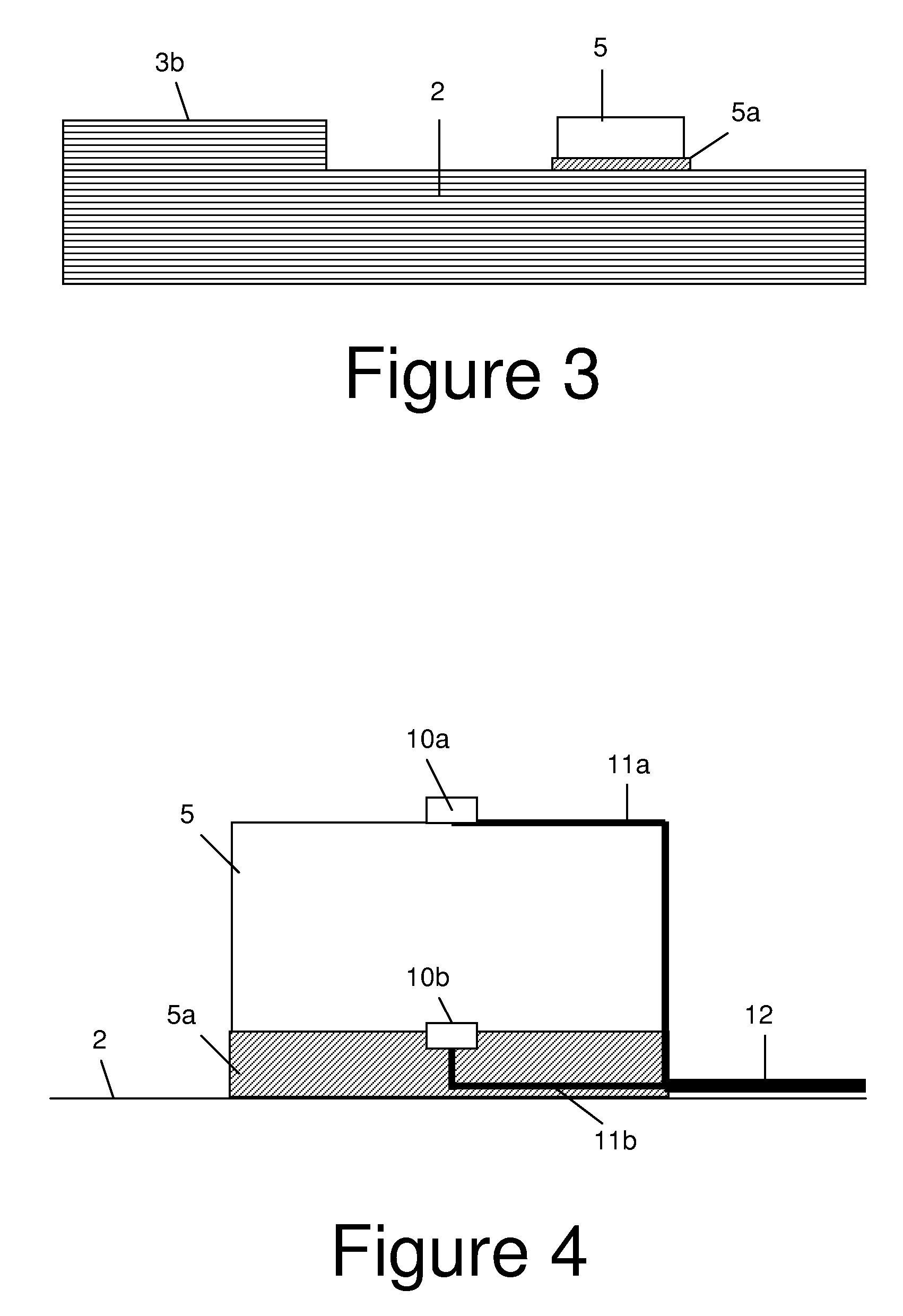
[0033]Each strain actuator 5 is bonded to the skin 1 by an adhesive layer 5a shown in FIGS. 3 and 4. A pair of electrodes 10a and 10b are bonded to the upper and lower faces of the actuator. Each electrode is connected to a respective control line 11a,11b and the control lin...


PUM


Abstract

A reinforced panel (1) comprising: a composite skin (2); a plurality of stringers (3, 4) bonded to the skin; and one or more strain actuators (5), each positioned between an adjacent pair of stringers. A load is applied to the panel in the plane of the skin, and a local strain is applied to the skin by the strain actuators when the compressive load exceeds a predetermined threshold. This causes the skin to buckle and reduce interface stresses between the skin and the stringers.

Description

[0001]This application is the U.S. national phase of International Application No. PCT / GB2008 / 050294 filed 24 Apr. 2008 which designated the U.S. and claims priority to British Patent Application No. 0709118.4 filed 14 May 2007, the entire contents of each of which are hereby incorporated by reference.FIELD OF THE INVENTION[0002]The present invention relates to a reinforced panel comprising a composite skin; and a plurality of stringers bonded to the skin. The invention also relates to a method of buckling such a reinforced panel.BACKGROUND OF THE INVENTION[0003]Despite their high level of performance in specific areas, such as weight, durability and through-life costs, composites are not widely accepted in primary structures. This is mostly due to a reduced understanding of the failure mechanisms and of their behaviour when damaged. This widespread lack of knowledge and know-how often leads to over sized structures, which are in contrast with the lightweight philosophy characterizi...

Claims


Application Information

Patent Timeline
06 Nov 2012
Publication
US8302486B2
IPC
G01G5/00; B64C1/00; G01M99/00
CPC
B64C1/12; B64C3/48; B64C3/26
Inventors
COSENTINO, ENZO