Spindle mechanism of winding machine

A technology of winding machine and spindle, which is applied in coil manufacturing, thin material processing, and delivery of filamentous materials, etc. It can solve problems such as difficult to improve, very high requirements for maintenance personnel using the manufacturer's equipment, damage, etc., to eliminate thermal expansion Cold shrinkage, simple assembly and disassembly replacement, and the effect of eliminating processing errors

Active Publication Date: 2017-11-24
XIAMEN HONGFA IND ROBOT CO LTD
View PDF12 Cites 4 Cited by
  • Summary
  • Abstract
  • Description
  • Claims
  • Application Information

AI Technical Summary

Problems solved by technology

The maximum speed of the winding machine can only reach 15000rpm, which is difficult to increase
Moreover, the main shaft of the existing structure will be damaged after being used 24 hours a day for about 3 years. When replacing the main shaft, the angular contact bearing must be replaced by a professional, which requires very high requirements for the maintenance personnel of the manufacturer's equipment.
The loss of personnel and production caused by the replacement of the spindle is unacceptable to the manufacturer

Method used


Image

  • Spindle mechanism of winding machine
  • Spindle mechanism of winding machine
  • Spindle mechanism of winding machine

Examples


Embodiment Construction

[0023] To further illustrate the various embodiments, the present invention is provided with accompanying drawings. These drawings are a part of the disclosure of the present invention, which are mainly used to illustrate the embodiments, and can be combined with related descriptions in the specification to explain the operating principles of the embodiments. With reference to these contents, those skilled in the art should understand other possible implementations and advantages of the present invention. Components in the figures are not drawn to scale, and similar component symbols are generally used to denote similar components.

[0024] The present invention will be further described in conjunction with the accompanying drawings and specific embodiments.

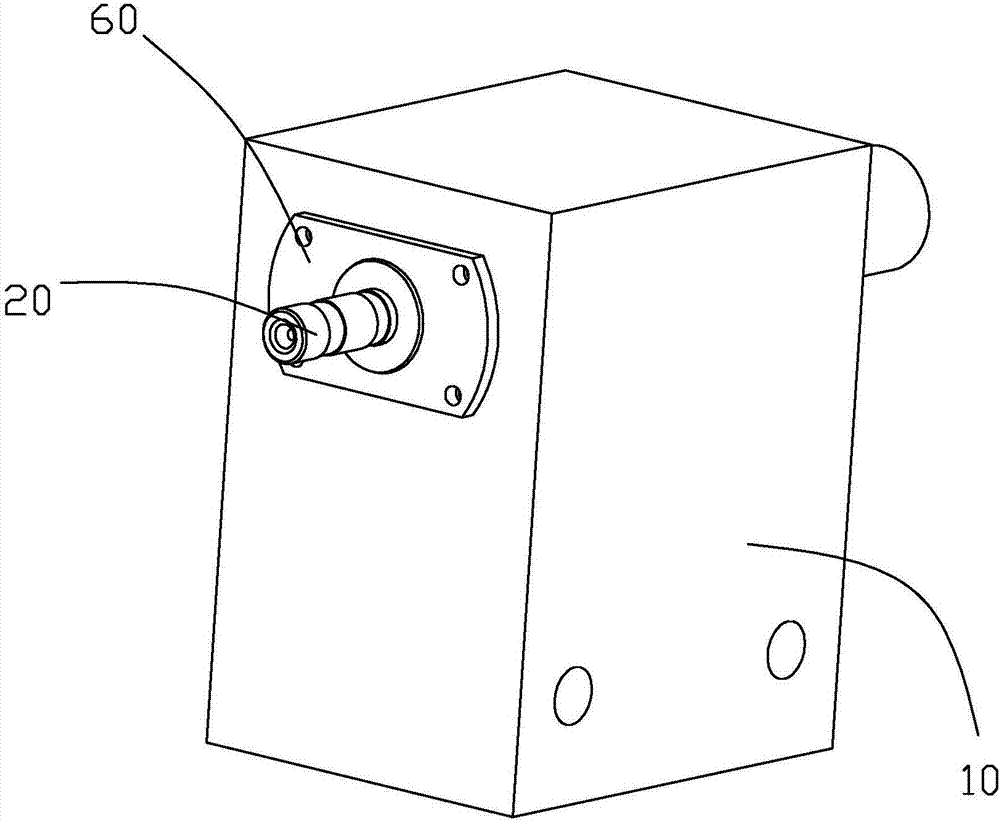
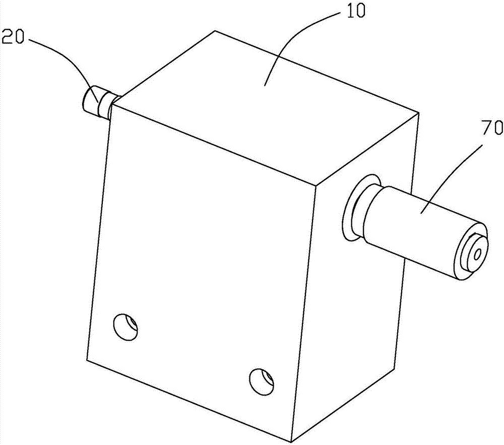
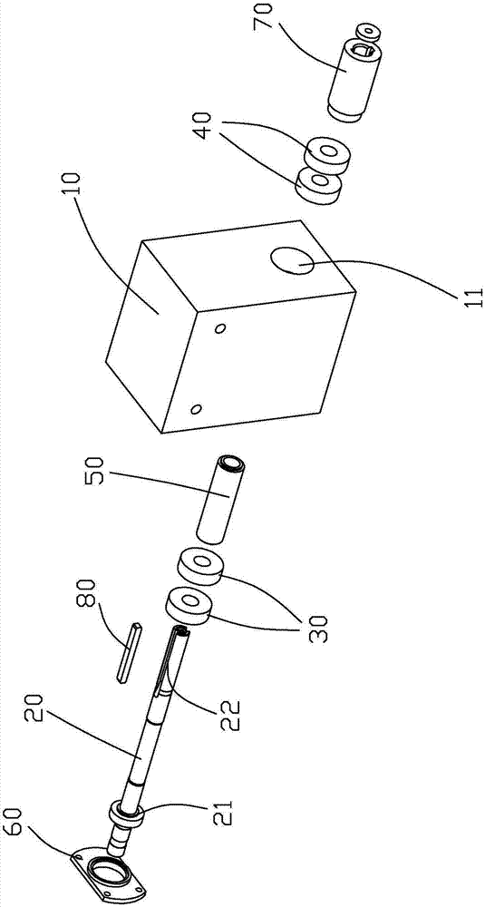
[0025] refer to Figure 1 to Figure 7 As shown, a winding machine spindle mechanism provided by the present invention includes: a spindle box 10, a spindle 20, a bearing, a shaft sleeve 50 and a bearing cover 60, and t...


PUM


Abstract

The invention provides a spindle mechanism of a winding machine. The spindle mechanism comprises a spindle box, a spindle and bearings, a mounting hole is formed in the spindle box, the spindle is penetratingly arranged in the mounting hole of the spindle box and rotatably arranged on the spindle box through the bearings, the bearings are arranged at two ends of the mounting hole of the spindle box to form a front-end bearing and a rear-end bearing respectively, the front-end bearing and the rear-end bearing are identical in number, and an outer ring of each bearing at least at one end is unlimited axially to form a free end. Through arrangement in this way, the spindle is more uniform in front and rear stress, and a foundation is laid for high-speed running; the outer ring of each bearing is in a free state axially, so that thermal expansion and cold contraction of parts caused by heat release of the bearings running at a high speed, and rotating speed of the spindle can be increased while frequency of being damaged can be reduced. In addition, the outer ring of each bearing is in the free state axially, so that processing errors can be eliminated, and assembling and disassembling are simpler.

Description

technical field [0001] The invention relates to the field of winding machines, in particular to a winding machine spindle mechanism which improves the rotating speed and service life of the winding machine spindle and reduces the difficulty of replacement. Background technique [0002] In the current market, winding machines are pursuing higher and higher spindle speeds due to mass production. One consequence of the increase in spindle speed is the damage caused by long-term high-speed operation of the bearings. As shown in the Chinese utility model patent application number 201420518252.9 of a winding machine spindle, the current winding machine spindle bearing arrangement structure is mostly three bearings, two angular contact bearings or deep groove ball bearings at the front end, and one at the rear end. Deep groove ball bearings, the rear end of the main shaft drives all the main shafts to rotate synchronously through the synchronous pulley. The maximum speed of the wi...

Claims


Application Information

Patent Timeline
Patent Type & Authority Applications(China)
IPC IPC(8): B65H54/40H01F41/06
CPCB65H54/40H01F41/06B65H54/106B65H54/44B65H2301/4132B65H2513/11B65H2402/52B65H75/18B65H2601/26B65H2402/20
Inventor 郭凡林廖建明张译丹白杰昌刘银华
Owner XIAMEN HONGFA IND ROBOT CO LTD
Why Eureka
Try Eureka