
Tunnel crane

A technology for cranes and tunnels, which is applied in the direction of cranes, traveling bridge cranes, load suspension components, etc., and can solve the problems of rising construction costs, increased construction volume, and the lack of track lifting operations, etc.

Active Publication Date: 2017-11-24
东台市富康机械有限公司
View PDF6 Cites 0 Cited by
  • Summary
  • Abstract
  • Description
  • Claims
  • Application Information

AI Technical Summary

Problems solved by technology

In order to facilitate the crane to carry out track laying and other operations, a certain lifting operation space is required at the construction site. For some construction sites with open ground and ample operating space, the crane can be used handy. For those special construction sites, such as urban Because of the circular shape of the light rail tunnel, it is very difficult for conventional lifting equipment to walk directly in it, not to mention the lifting operation on the track. In order to ensure that conventional cranes can carry out construction in it, it is often necessary Pre-construct two construction runways in the tunnel and dismantle them after the construction is completed. The construction and dismantling of the construction runways is not only time-consuming and labor-intensive, but also consumes a lot of building materials, which directly leads to an increase in the construction cost and construction volume.
From the perspective of allowing the crane to walk directly in the tunnel for lifting operations, saving engineering costs, reducing the amount of construction, and facilitating construction, relevant crane manufacturers have developed some special cranes for tunnel track laying, but there is no structure or site. Unsatisfactory in terms of reliability and effect

Method used


Image

  • Tunnel crane
  • Tunnel crane
  • Tunnel crane

Examples


Embodiment Construction

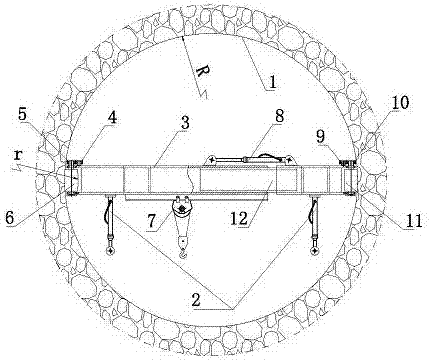
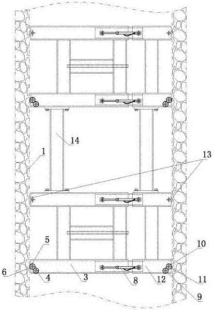
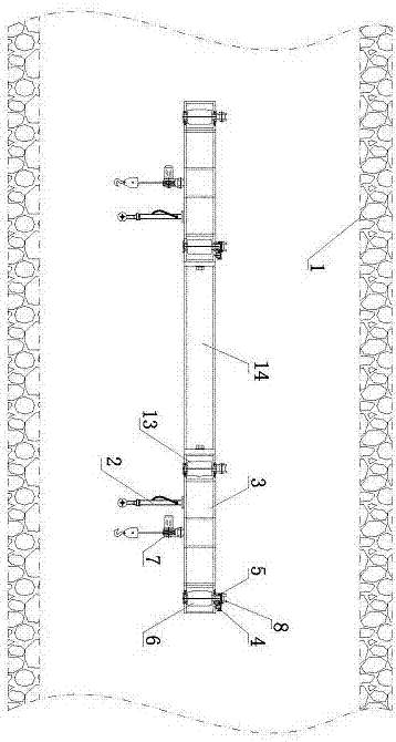
[0014] figure 1 , figure 2 and image 3 In the shown tunnel crane, the girder includes an outer girder 3 and an inner girder 12, the connecting end of the outer girder 3 can be slidably socketed on the connecting end of the inner girder 12, and on the girder A telescopic oil cylinder 8 is provided, and one end of the telescopic oil cylinder 8 is twisted and supported on the outer beam frame 3 , and the other end of the telescopic oil cylinder 8 is twisted and supported on the inner layer beam frame 12 . A rotatable left driving roller 6 is arranged on the supporting end of the outer beam frame 3, and a left driving gear 5 is fixedly arranged on the left driving roller 6, and the left driving gear 5 meshes with the left driving gear 4, and the left driving gear 4. Fixedly connected to the hydraulic motor; a rotatable right driving roller 11 is arranged on the support end of the inner beam frame 12, and a right transmission gear 10 is fixedly arranged on the right driving rol...


PUM


Abstract

The invention discloses a tunnel crane which comprises a beam frame. The beam frame includes an outer beam frame body and an inner frame beam body, the connecting end of the outer beam frame body is slidably connected with the connecting end of the inner beam frame body in a sleeving manner, a left driving roller is arranged at the support end of the outer beam frame layer, a right driving roller is arranged at the support end of the inner beam frame body, both the left driving roller and the right driving roller are connected to a driving device in a transmission manner, a beam frame retraction device is arranged on the beam frame, two ends of the beam frame retraction device are respectively hinged to the outer beam frame body and the inner beam frame body, and a movable winch is arranged on the beam frame. By the arrangement, the tunnel crane can travel in a tunnel directly for lifting operations, and the tunnel crane is reasonable in structural design and safe and reliable in use.

Description

technical field [0001] The invention relates to a construction machine, in particular to a crane used for laying a track in a tunnel. Background technique [0002] During the track construction process, the application of lifting equipment is essential in order to facilitate the movement and laying of the track. With the development of technology, various cranes for special construction environments and special construction needs have emerged, and quite a few of them are very mature, which greatly facilitates construction and plays a role in escorting the safety and progress of construction. In order to facilitate the crane to carry out track laying and other operations, a certain lifting operation space is required at the construction site. For some construction sites with open ground and ample operating space, the crane can be used handy. For those special construction sites, such as urban Because of the circular shape of the light rail tunnel, it is very difficult for co...

Claims


Application Information

Patent Timeline
IPC IPC(8): B66C17/06B66C6/00
CPCB66C6/00B66C17/06
Inventor 彭洪崔益祥游有鹏杨原金游万钧张义军
Owner 东台市富康机械有限公司
Learn More