
Wind driven generator

A technology for wind turbines and generators, which is applied to wind turbines, wind turbine combinations, wind energy power generation, etc., can solve the problems that wind turbines cannot be found in time, and the anti-vibration effect of generator shafts is poor.

Inactive Publication Date: 2017-11-24
JIANGSHAN XIANJIN ELECTRICAL & MECHANICAL TECH SERVICES CO LTD
View PDF0 Cites 2 Cited by
  • Summary
  • Abstract
  • Description
  • Claims
  • Application Information

AI Technical Summary

Problems solved by technology

[0003] The invention provides a wind power generator that can detect in time when the seal ring with good shock resistance of the generator rotating shaft fails to leak, and can effectively prevent hydraulic oil from leaking to the brake ring after leakage occurs, which solves the problem of existing wind power generators. The problem of not being able to find out in time when leakage occurs and the poor anti-vibration effect of the generator shaft

Method used


Image

  • Wind driven generator
  • Wind driven generator
  • Wind driven generator

Examples


Embodiment Construction

[0020] The present invention will be further described below in conjunction with the accompanying drawings and embodiments.

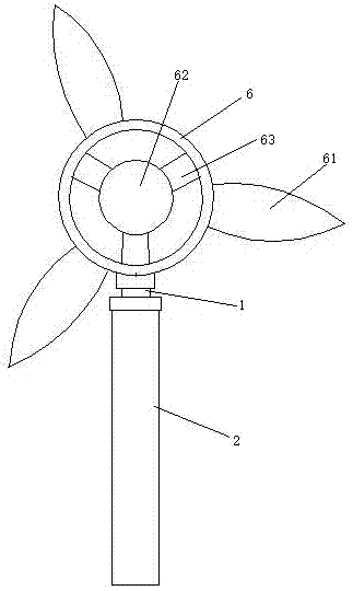
[0021] see figure 1 , a wind generator, including a column 2, a chassis 6 connected to the column through a yaw bearing 1, a generator (not shown in the figure) located in the chassis, and wind blades 61 that drive the generator to generate electricity. Three damping supports 63 are arranged between the rotating shaft 62 of the generator and the casing 6 . The shock-absorbing support 63 is three rubber pads.

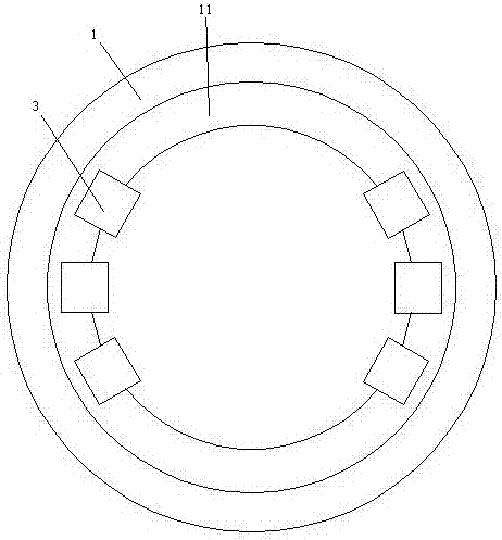
[0022] see figure 2 , also includes several brake units 3. The yaw bearing 1 is provided with a brake ring 11 .

[0023] There are six brake units 3. Three of the six brake units 3 are arranged on the front side of the brake ring 11 , and the other three brake units 3 are arranged on the rear side of the brake ring 11 .

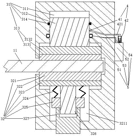
[0024] see image 3 , The brake unit 3 includes a hydraulic brake 31 and a spring brake 32 . The hydraulic brake 31 is...


PUM


Abstract

The invention relates to a wind power generation technology. A wind driven generator comprises brake units, a stand column, a case connected with the stand column through a yaw bearing, a power generator located inside the case, and fan blades for driving the power generator to generate power. The yaw bearing is connected with a brake ring. Each brake unit comprises a hydraulic brake and a spring brake, wherein the hydraulic brake comprises a dynamic sealing ring, a brake oil cylinder, a piston, a hydraulic brake part friction plate and a leakage detection mechanism; the spring brake comprises a spring brake part friction plate and a spring; the leakage detection mechanism comprises an annular oil groove, an oil tank and a detection mechanism; and the dynamic sealing ring comprises an inflation sealing ring and an air source. The wind driven generator has the advantages that a rotary shaft of the power generator is good in shock resistance, when a sealing ring fails and leakage occurs, leakage can be found in time, and hydraulic oil is effectively prevented from leaking on the brake ring after leakage is generated, and the problems that when leakage happens to an existing wind driven generator, leakage cannot be found in time and the shock resistance effect of a rotary shaft of the existing wind driven generator is poor are solved.

Description

technical field [0001] The invention relates to wind power generation technology, in particular to a wind power generator. Background technique [0002] A structure of a wind power generator includes a brake unit, a column, a chassis connected to the column through a yaw bearing, a generator located in the chassis, and wind blades that drive the generator to generate electricity. The yaw bearing is connected with a matching mechanism. The brake ring of the moving unit for friction braking. When the wind turbine is in use, the direction of the wind blades is adjusted and fixed through the rotating unit and the brake ring, so that the wind turbine can face the wind accurately. The braking unit of the existing wind power generator is completely provided with hydraulic braking and residual pressure to provide damping torque. When the seal ring fails and causes leakage, it cannot be found in time until it cannot be used. The anti-seismic effect of the rotating shaft of the gene...

Claims


Application Information

Patent Timeline
Patent Type & Authority Applications(China)
IPC IPC(8): F03D9/25F03D7/02F03D17/00F03D80/70F16D55/228F16D65/18F16D66/00F16D121/04
CPCF03D7/0204F03D7/0244F03D7/0296F03D9/25F03D17/00F03D80/70F16D55/228F16D65/18F16D66/00F16D2121/04Y02E10/72
Inventor 危金兰
Owner JIANGSHAN XIANJIN ELECTRICAL & MECHANICAL TECH SERVICES CO LTD
Learn More