Micro flow regulating valve

A flow regulating valve, tiny technology, applied in the direction of lifting valve, valve detail, valve device, etc., can solve the problems of strength reduction, easy breakage, etc., and achieve the effect of reasonable structure setting, good sealing performance and reasonable structure design

Pending Publication Date: 2017-11-24
ZHEJIANG BEIER CONTROL VALVE
View PDF9 Cites 1 Cited by
  • Summary
  • Abstract
  • Description
  • Claims
  • Application Information

AI Technical Summary

Problems solved by technology

[0002] Most of the small flow regulating valves use changing the shape of the spool to adjust the flow of the valve. When the medium pressure is high and the temperature is high and the flow is small, it is necessary to make the spool very small to achieve the required small flow. If the core is made very small, its strength will be greatly reduced, and it will easily break when the pressure difference is large and the flow rate is high, which will easily bring serious consequences.
For example, the applicant applied for the invention patent with the patent number 201220622597.X and the patent name "small flow high pressure regulating valve" on November 22, 2012, which has the above technical problems and cannot be effectively solved

Method used


Image

  • Micro flow regulating valve
  • Micro flow regulating valve
  • Micro flow regulating valve

Examples


Embodiment Construction

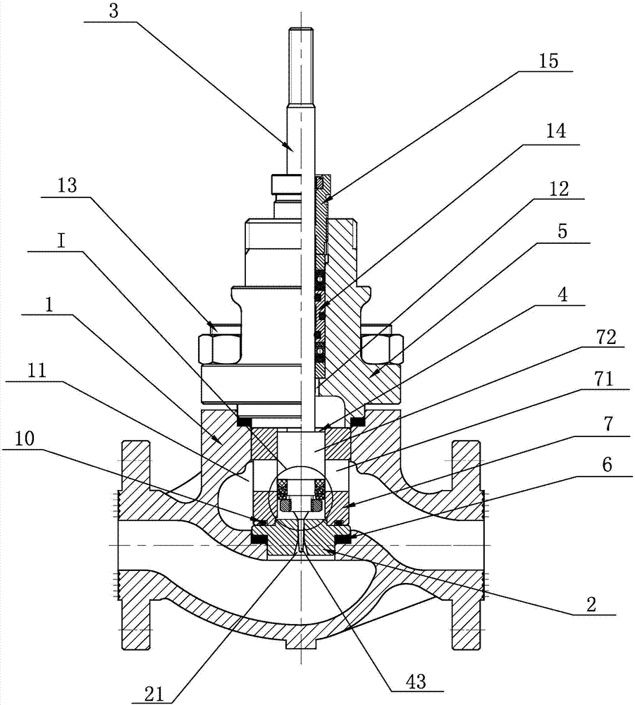
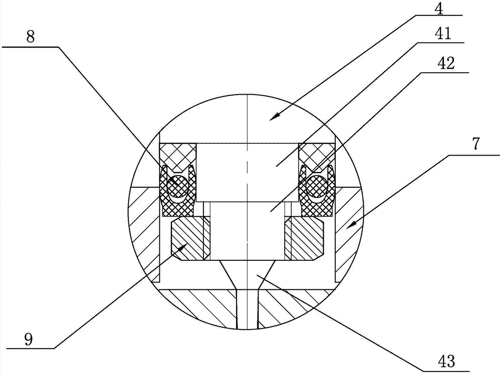
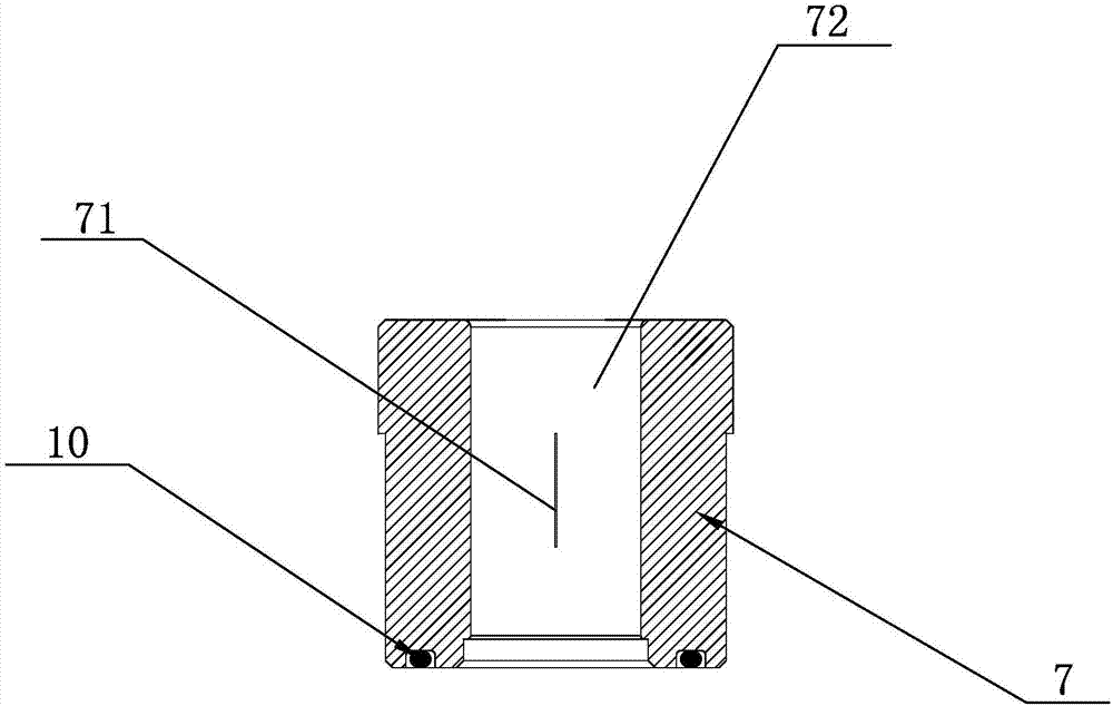
[0018] See figure 1 , figure 2 with image 3 , The present invention discloses a micro flow regulating valve, comprising a valve body 1, a valve seat 2, a valve stem 3, a valve core 4 and a valve cover 5. The valve body 1 is provided with a valve body cavity 11, and the valve A valve seat gasket 6 is provided at the lower end of the body cavity 11, a valve seat 2 is installed on the valve seat gasket 6, a small flow guide valve cage 7 is provided at the upper end of the valve seat 2, and the lower end of the valve cover 5 is connected to The small flow guide valve cage 7 is connected, and the small flow guide valve cage 7 is compressed by locking the valve cover 5. A valve stem mounting hole 12 is vertically provided in the middle of the valve cover 5, and the valve stem 3 penetrates In the valve stem mounting hole 12, the lower end of the valve stem 3 and the valve core 4 are integrally arranged, and the lower end of the valve core 4 is detachably provided with a valve core s...


PUM


Abstract

The invention discloses a micro flow regulating valve which comprises a valve body, a valve seat, a valve stem, a spool and a bonnet. A valve body center cavity is formed in the valve body; a valve seat gasket is arranged at the lower end of the valve body center cavity; the valve seat is mounted on the valve seat gasket; a micro flow guide valve cage is arranged at the upper end of the valve seat; the lower end of the bonnet is connected with the micro flow guide valve cage. A valve stem mounting hole is formed in the middle of the valve body vertically; the valve stem penetrates the valve stem mounting hole; the spool is arranged at the lower end of the valve stem integrally; the lower end of the spool is detachably provided with a spool seal ring. Besides, the micro flow guide valve cage is provided with an elongated slit, the valve stem drives the spool to move up and down, the spool drives the spool seal ring to move relative to the elongated slit, so that the flow area of the elongated slit is changed and flow change is achieved. According to the technical scheme, the micro flow regulating valve has the advantages of reasonable design, simple structure, good sealing performance, convenience in use, high safety and reliability and long service life; the spool thereof is not easy to damage.

Description

Technical field [0001] The invention relates to the technical field of valves, in particular to a small flow regulating valve. Background technique [0002] Most small flow control valves use the shape of the valve core to adjust the flow of the valve. When the medium pressure is high, the temperature is high and the flow is very small, the valve core needs to be made small to achieve the required small flow. If the core is small, its strength is greatly reduced, and it is easy to break when the pressure difference is large and the flow rate is high, which is likely to bring serious consequences. For example, if the applicant applied for the patent number 201220622597.X and the invention patent with the patent name "small flow and high pressure regulating valve" on November 22, 2012, the above technical problems cannot be effectively solved. Summary of the invention [0003] In view of the shortcomings of the prior art, the purpose of the present invention is to provide a small f...

Claims


Application Information

Patent Timeline
Patent Type & Authority Applications(China)
IPC IPC(8): F16K1/32F16K1/46F16K1/48F16K1/42F16K41/02
CPCF16K1/32F16K1/42F16K1/46F16K1/48F16K41/02
Inventor 林童林峰王平红舒婷洁李红伟谢钦辉
Owner ZHEJIANG BEIER CONTROL VALVE
Why Eureka
Try Eureka