An infrared touch module and an infrared touch display device

An infrared touch and display device technology, which is applied in the fields of instruments, computing, electrical and digital data processing, etc., can solve the problems of increasing structural complexity, overall aesthetic product cost, and cannot guarantee the reliability of infrared touch structure connection, etc. Reduce the number, facilitate narrow frame, and ensure the effect of fixing reliability

Active Publication Date: 2021-03-02
TCL CHINA STAR OPTOELECTRONICS TECH CO LTD
View PDF6 Cites 0 Cited by
  • Summary
  • Abstract
  • Description
  • Claims
  • Application Information

AI Technical Summary

Problems solved by technology

[0003] In the current commercial display market, display screens generally require touch functions in end-customer applications. Ordinary display screens usually use touch screens with infrared technology. However, since the infrared touch structure is usually integrated and fixed to the display as a separate module On the screen, the display screen cannot guarantee the reliability of the connection of the infrared touch structure. In order to make up for this defect, many auxiliary reinforcements are often used to fix between the display screen and the infrared touch structure, but this also directly increases the structural reliability. Complexity, overall aesthetics, and cost of the product

Method used


Image

  • An infrared touch module and an infrared touch display device
  • An infrared touch module and an infrared touch display device
  • An infrared touch module and an infrared touch display device

Examples


Embodiment Construction

[0020] In order to make the object, technical solution and advantages of the present invention more clear, the present invention will be further described in detail below in conjunction with the accompanying drawings and embodiments. It should be understood that the specific embodiments described here are only used to explain the present invention, not to limit the present invention.

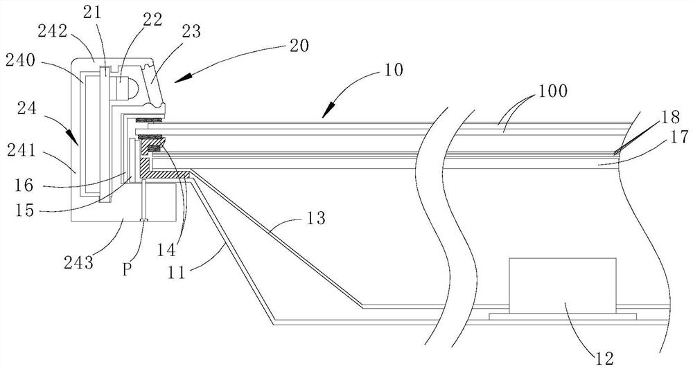
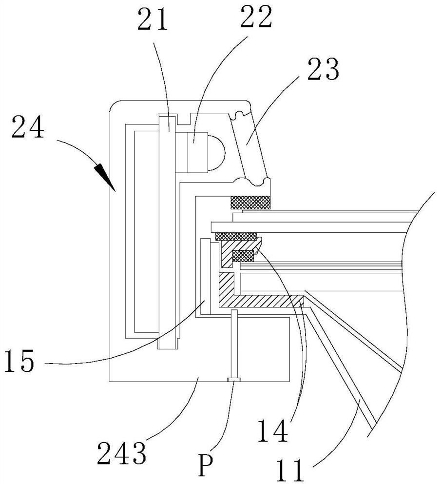
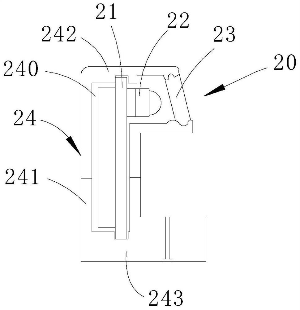
[0021] refer to figure 1 , the infrared touch display device of the embodiment of the present invention includes a display module 10 and an infrared touch module 20, the display module 10 has a display screen, and its surroundings are embedded in the display module 10, and are relatively fixed to the housing 24 through a connector , the infrared touch module 20 is located on the periphery of the display module 10 and is used to provide the display module 10 with a touch operation function.

[0022] The infrared touch module 20 includes a circuit board 21, an infrared point light source 22, an o...


PUM


Abstract

The invention discloses an infrared touch module, which comprises a circuit board, an infrared point light source, an optical lens and a casing. The infrared point light source is mounted on the circuit board. The upper and lower ends of the upper and lower ends are bent toward the middle of the frame structure to the first frame edge and the second frame edge; there is a groove running through the end face of the first frame edge in the housing, and the circuit board and the infrared point light source are accommodated in the groove, and the infrared The point light source faces the outlet of the groove; a slot for inserting the end of the display device is formed between the first frame side and the second frame side. The invention also discloses an infrared touch display device. The periphery of the display device is inserted into the slot of the infrared touch module and fixed relatively to the infrared touch module, which can ensure the reliability of the infrared touch module. At the same time, it avoids the use of various fixing structures for fixing, reducing structural parts The vertically installed circuit board in the infrared touch module is also conducive to the narrow frame design of the infrared touch display device.

Description

technical field [0001] The invention relates to the field of display technology, in particular to an infrared touch module and an infrared touch display device. Background technique [0002] Infrared multi-touch (IRMT) technology is to detect and locate a person's touch gestures by using an infrared matrix densely distributed in the X and Y directions. The infrared touch screen is mainly to install the circuit board frame in front of the display. The receiving tubes correspond to each other on opposite sides of the screen, forming a horizontal and vertical infrared matrix. When the finger touches the screen, it will block the two infrared rays passing through the position, so the coordinate position of the touch point on the screen can be judged. The advantage of this kind of touch screen is that any non-transparent object can change the position on the touch point. Infrared to achieve touch screen operation. [0003] In the current commercial display market, display scre...

Claims


Application Information

Patent Timeline
Patent Type & Authority Patents(China)
IPC IPC(8): G06F3/042
CPCG06F3/0421
Inventor 陈伟丰唐国富周明军
Owner TCL CHINA STAR OPTOELECTRONICS TECH CO LTD
Why Eureka
Try Eureka