Assembled type concrete structure three-dimensional collaborative design method

A technology of concrete structure and collaborative design, applied in computing, image data processing, special data processing applications, etc., can solve problems such as insufficient meeting the requirements of building structure form, lack of design ideas, restricting prefabricated structures, etc. Type component modeling and drawing time, shortening modeling and drawing time, and improving efficiency

Active Publication Date: 2017-11-24
CHINA CONSTR FIRST DIV GROUP CONSTR & DEV
View PDF5 Cites 42 Cited by
  • Summary
  • Abstract
  • Description
  • Claims
  • Application Information

AI Technical Summary

Problems solved by technology

In the design of prefabricated concrete structures, the traditional method is to complete the drawing in the CAD two-dimensional plane. First, the drawing efficiency is low, error-prone, and the modification is highly repetitive. Secondly, the designer is required to have a strong spatial thinking ability, which is not enough Meet the increasingly complex and changeable architectural structure requirements, which greatly limits the development of prefabricated structures
In addition, since it is necessary to comprehensively consider various professional information before component production, it is necessary to clearly reflect various reserved and embedded information in the drawings, which also means that traditional two-dimensional design ideas are difficult to meet this rigidity. Requirements, it is necessary to lean towards three-dimensional design; at the same time, the prefabricated building has not yet formed a complete and clear set of design ideas, which urgently needs to be summarized and condensed

Method used


Image

  • Assembled type concrete structure three-dimensional collaborative design method
  • Assembled type concrete structure three-dimensional collaborative design method
  • Assembled type concrete structure three-dimensional collaborative design method

Examples


Embodiment Construction

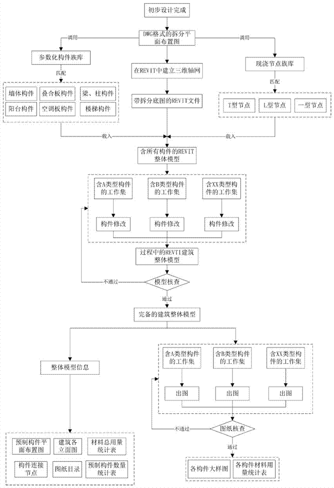
[0035] The method proposed in this invention is applicable to fabricated concrete structures, including shear wall structures and frame structures. Here we only take the assembled integral shear wall structure as an example for illustration. It should be noted that all the operation processes involved in this method are completed based on the network storage environment. The relevant process of this method is described in detail as follows:

[0036] 1. Complete the split design of the prefabricated building according to the schematic design and drawings after the preliminary design is completed

[0037] Main operation process:

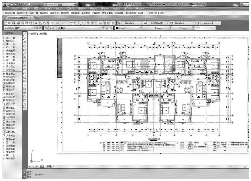
[0038] ① if figure 2 As shown, start the AutoCAD program, click the open option in the menu bar, and select the project structure drawing in .dwg format (Beijing XX project structure drawing) in the file selection pop-up box;

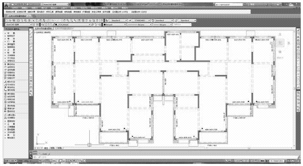
[0039] ② if image 3 As shown in , create a new structure split edge layer, complete the split layout of the correspondi...


PUM


Abstract

The invention discloses an assembled type concrete structure three-dimensional collaborative design method. The assembled type concrete structure three-dimensional collaborative design method comprises the steps of completing assembled type building splitting design according to drawing data, preparing a Revit item center file, establishing parameter models of a prefabricated member and a cast-in-situ node, loading the parameter member and the cast-in-situ node into a Revit item center file to form an overall model, revising members of all types, completing model overall information input and single member plotting and the like. Based on a Revit platform, by establishing a visualized three-dimensional entity model, then design, revising and plotting are conducted through a synergetic mode. The assembled type concrete structure three-dimensional collaborative design method has the following advantages that regardless of a two-dimensional abstract drawing mode, visualized three-dimensional modeling is achieved; the same model jointly represents all profession information, professional interaction is achieved, and repetitive adjusting and revising is avoided; modeling and plotting time of members of the same type is shortened, the efficiency is improved, the quality is unified, and management is facilitated.

Description

technical field [0001] The invention relates to the field of construction engineering, in particular to a three-dimensional collaborative design method for a prefabricated concrete structure. Background technique [0002] In recent years, with the country's increasing emphasis on prefabricated buildings, there will be a climax of prefabricated design in China in the future. The prefabricated building refers to the building structure in which the components are pre-produced in the component factory, then transported to the site for lifting and installation, and finally realized. In the design of prefabricated concrete structures, the traditional method is to complete the drawing in the CAD two-dimensional plane. First, the drawing efficiency is low, error-prone, and the modification is highly repetitive. Secondly, the designer is required to have a strong spatial thinking ability, which is not enough To meet the increasingly complex and changeable architectural structure req...

Claims


Application Information

Patent Timeline
Patent Type & Authority Applications(China)
IPC IPC(8): G06F17/50G06T17/00G06T19/20
CPCG06T17/00G06T19/20G06T2210/04G06T2219/2008G06F30/13
Inventor 李贝姚博强杨嘉伟吕雪源袁齐
Owner CHINA CONSTR FIRST DIV GROUP CONSTR & DEV
Why Eureka
Try Eureka