
Thin switch

A thin switch and contact shrapnel technology, applied in the field of switches, can solve the problems of large overall thickness, uneven force, slow response, etc., and achieve the effect of less overall component composition, increased use feeling, and less component composition

Active Publication Date: 2017-11-24
刘二军
View PDF7 Cites 2 Cited by
  • Summary
  • Abstract
  • Description
  • Claims
  • Application Information

AI Technical Summary

Problems solved by technology

The thin mechanical keyboard for laptop computers connects the keycap and the reinforced iron plate respectively through the scissors feet, and keeps the balance of the keycaps by the scissors feet in the process of pressing down the keycaps, and realizes the strike through the sound parts and contact shrapnels vertically arranged in the base. The sound of the sound and the conduction of the line, the vertically arranged sound parts and the contact shrapnel are placed in the base with the push button, which has the following disadvantages: 1. Due to the large thickness of the push button and the vertical arrangement of the contact shrapnel, its It is difficult to reduce the thickness, and the thickness of the base makes the overall thickness of the whole switch larger, which does not conform to the current trend of thinning; 2. The sound part of this key switch is set on one side of the base. When the user applies pressure, The force is uneven during the pressing down process, which is easy to damage the parts, and then affects the service life of the key switch; 3. The contact is located at the lower part of the contact piece, and the response is slow and the sensitivity is poor during the pressing down process.

Method used


Image

  • Thin switch
  • Thin switch
  • Thin switch

Examples


Embodiment 1

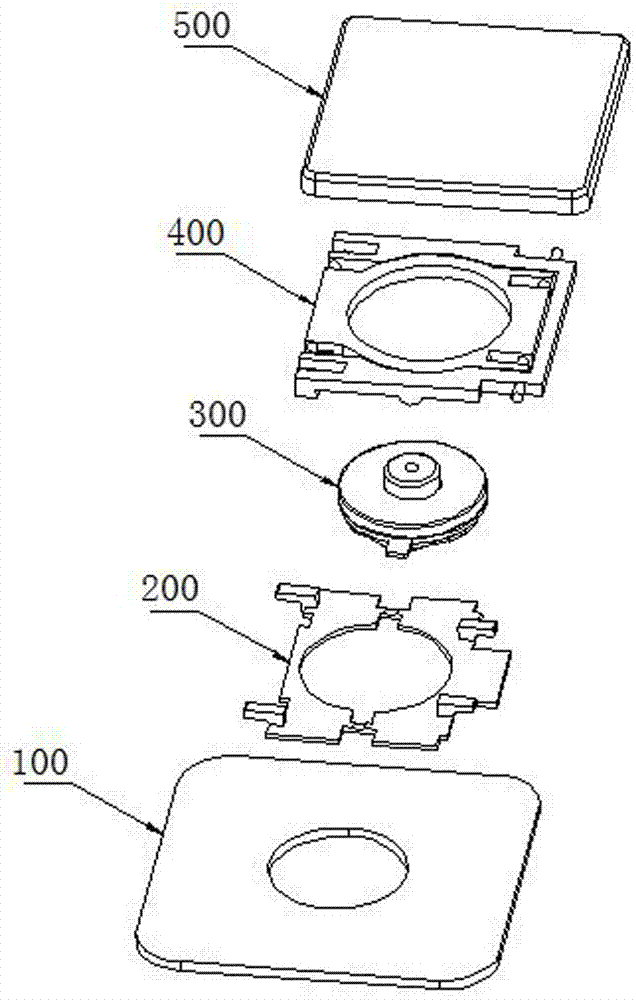
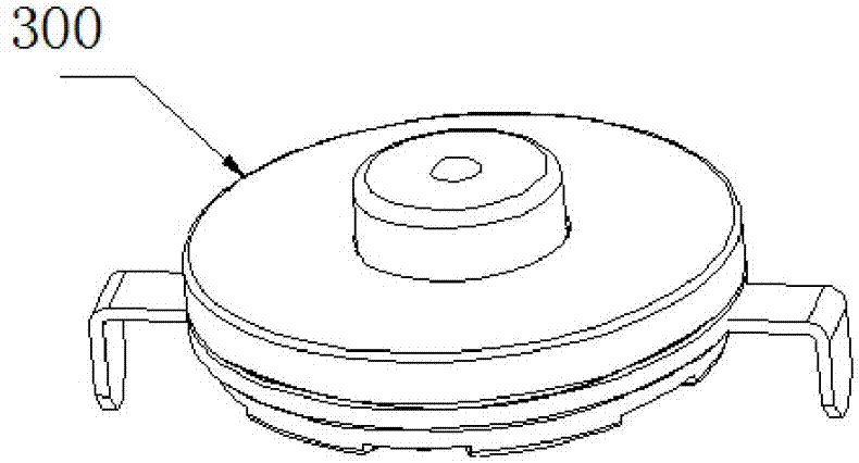
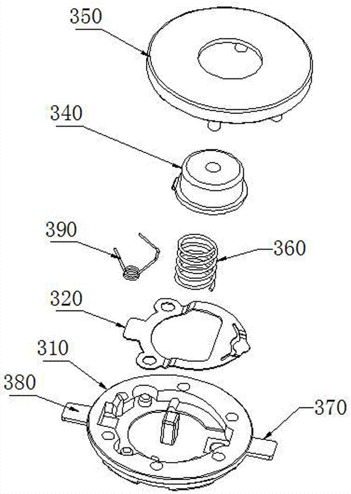
[0046] like Figure 1 to Figure 9 As shown, a thin switch, the thin switch 300 is connected to the circuit board 100 on the keyboard, the keyboard includes: a bottom plate assembly, the bottom plate assembly includes a circuit board 100 and a support plate 200; a plurality of keys, the The buttons are arranged on the base plate assembly, and each button is provided with: a keycap 500 in sequence from top to bottom; Contact connection, the bottom of the scissors feet 400 is connected with the support plate 200; a thin switch 300 connected with the circuit board 100, the thin switch 300 includes: a cover 350, the center of the cover 350 is provided with a button hole 351; Push button 340, the button button 340 is loaded into the button button hole 351 on the cover 350; a base 310, the base 310 is connected with the cover 350 by riveting, and the center of the base 310 is provided with a housing groove for contact shrapnel 315, the base groove wall 311 is surrounded by the conta...

Embodiment 2

[0053] like figure 1 , Figure 11 to Figure 15 As shown, the structure and principle of this embodiment are basically the same as that of Embodiment 1, the difference is that in this embodiment, a single-hole torsion spring 390 is used as the sound member, and the single-hole torsion spring 390 includes a second spring positioning The hole 391 , a second guiding portion 392 arranged obliquely and a third guiding portion 393 , the second guiding portion 392 is in contact with the arc-shaped extrusion contact 342 . On the base groove wall 311 between the upper moving terminal 380 of the base 310 and the base positioning hole 316 on one side, a sound piece guide column 318 is provided, and the sound piece guide column 318 is provided with a sound piece on the side corresponding to the sound piece. The member guiding inclined surface 319 is in contact with the third guiding portion 393 on the single-hole torsion spring 390 . The structure and principle of this embodiment are bas...


PUM


Abstract

The invention discloses a thin switch, comprising a surface cover, a press part, a base, a sounding piece and a contact spring, wherein the surface cover is provided with a press hole in the center; the press part is mounted in the press hole of the surface cover; the base is connected with the surface cover by riveting, the base is provided with a contact spring accommodating groove in the center, and the circumference of the contact spring accommodating groove is a base groove wall; the sounding piece is located on the base groove wall; the contact spring is horizontally arranged in the contact spring accommodating groove, the top of the contact spring is lower than the upper surface of the base, and the conducting part of the contact spring is located on the side of the base. The thin switch has the advantages of simple structure, low thickness, good user experience and the like.

Description

technical field [0001] The invention relates to a switch, in particular to a thin switch. Background technique [0002] The keyboard is a kind of computer peripheral equipment. The keyboard has a plurality of keys, and signals or instructions are input and transmitted to the computer by pressing the plurality of keys. Existing thin mechanical keyboards, such as the Chinese patent application titled "thin mechanical keyboard for laptop computers" with application number 2015100926090, disclose a thin mechanical keyboard for laptop computers, including circuit boards, scissor feet, keycaps, bases, and buttons. Zhi switch, spring, shell, etc., the circuit board is equipped with a reinforced iron plate, the reinforced iron plate has a hollow groove and a plurality of clamping parts at the corners, and a plurality of clamping parts are arranged on the scissors feet. The first positioning part and the second positioning part, the first positioning part is movably clamped on the c...

Claims


Application Information

Patent Timeline
Patent Type & Authority Applications(China)
IPC IPC(8): H01H13/84H01H13/7073
CPCH01H13/04H01H13/10H01H13/20H01H13/705H01H13/7073H01H13/84H01H2215/03H01H2223/034H01H2227/036
Inventor 刘二军
Owner 刘二军
Learn More