Antenna structure and mobile terminal

An antenna structure and mobile terminal technology, which are applied to antennas, antenna grounding devices, and devices that enable antennas to work in different frequency bands at the same time, can solve problems such as antenna bandwidth and efficiency reduction, improve antenna performance, meet usage requirements, and optimize The effect of using the experience

Inactive Publication Date: 2017-11-24
VIVO MOBILE COMM CO LTD
View PDF4 Cites 15 Cited by
  • Summary
  • Abstract
  • Description
  • Claims
  • Application Information

AI Technical Summary

Problems solved by technology

[0004] Embodiments of the present invention provide an antenna structure and a mobile terminal to so...

Method used


Image

  • Antenna structure and mobile terminal
  • Antenna structure and mobile terminal
  • Antenna structure and mobile terminal

Examples


Embodiment Construction

[0040] The following will clearly and completely describe the technical solutions in the embodiments of the present invention with reference to the accompanying drawings in the embodiments of the present invention. Obviously, the described embodiments are some of the embodiments of the present invention, but not all of them. Based on the embodiments of the present invention, all other embodiments obtained by persons of ordinary skill in the art without creative efforts fall within the protection scope of the present invention.

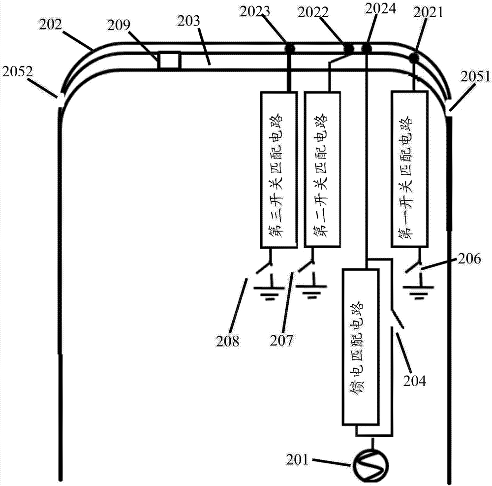
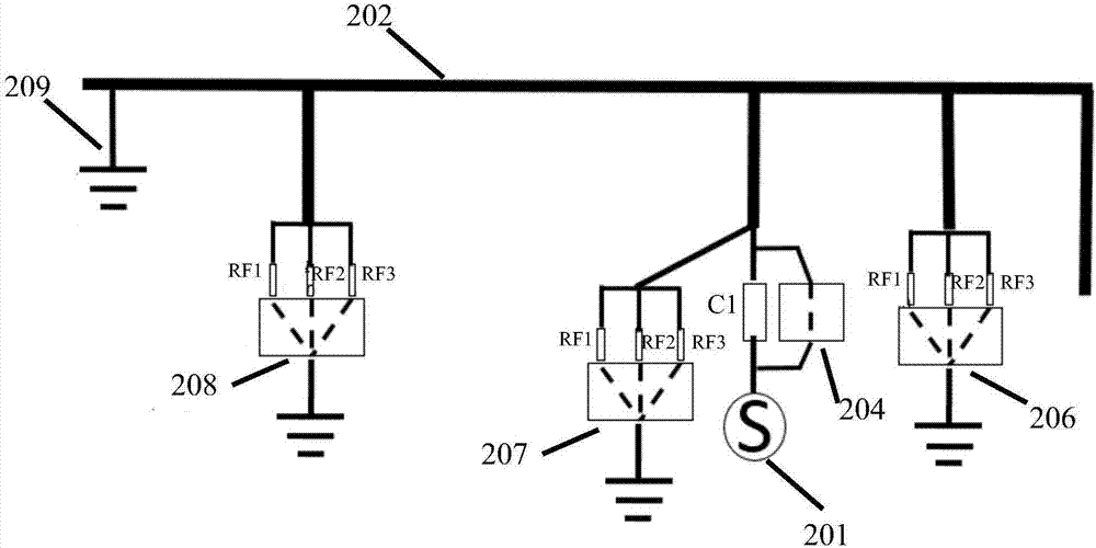
[0041] Such as figure 2 As shown, an antenna structure according to an embodiment of the present invention includes:

[0042] Antenna feed 201;

[0043] Antenna radiating arm 202;

[0044] The first end is connected to the antenna feed 201, and the second end is connected to the feed switch 204 of the antenna radiation arm 202; and

[0045] Control switches correspondingly connected to multiple ground points on the antenna radiating arm 202 .

[0...


PUM


Abstract

The invention, which relates to the technical field of communication, provides an antenna structure and a mobile terminal. The antenna structure comprises an antenna feed source, an antenna radiation arm, a feed switch, and control switches. A first end of the feed switch is connected to the antenna feed source and a second end is connected with the antenna radiation arm. The control switches are connected with a plurality of ground points on the antenna radiation arm correspondingly. Therefore, problems of antenna bandwidth and efficiency reduction of the existing antenna structure are solved.

Description

technical field [0001] The invention relates to the field of communication technology, in particular to an antenna structure and a mobile terminal. Background technique [0002] With the development of communication technology, the functions of mobile terminals are more diversified. In addition to basic communication, they also have functions such as photography, network information browsing, shopping, entertainment, etc., which bring great convenience to people's life. Mobile terminals have become an indispensable part of life. In recent years, the emergence of mobile terminals with all-metal bodies has been favored by the public due to their increased texture and outstanding appearance advantages. [0003] In order to solve the problem of signal reception, the staff designed a certain gap based on the body shell to ensure that the mobile terminal signal of the metal body is not shielded. In the existing antenna structure, the setting of the slot 101 is as follows figure...

Claims


Application Information

Patent Timeline
IPC IPC(8): H01Q5/335H01Q5/328H01Q1/48
CPCH01Q5/335H01Q1/48H01Q5/328
Inventor 蒋锐
Owner VIVO MOBILE COMM CO LTD
Why Eureka
Try Eureka