
Rotor and servo motor

A servo motor and rotor technology, applied in the direction of magnetic circuit rotating parts, magnetic circuit shape/style/structure, etc., can solve the problems of unfavorable motor efficiency and heat dissipation performance, reduction of glue bonding performance, motor loss and increase in heat of the whole machine. Large problems such as high efficiency, heat dissipation, reduction of magnetic circuit reluctance, and reduction of cogging torque are achieved.

Pending Publication Date: 2017-11-24
ZHUHAI GREE REFRIGERATION TECH CENT OF ENERGY SAVING & ENVIRONMENTAL PROTECTION
View PDF7 Cites 5 Cited by
  • Summary
  • Abstract
  • Description
  • Claims
  • Application Information

AI Technical Summary

Problems solved by technology

[0004] 1. When the motor is under long-term load or overload, the surface temperature of the rotating shaft will rise, which will reduce the bonding performance of the glue, and there will be a risk of glue failure, causing the magnetic ring to move or even fly out, which may cause the motor to lose control;
[0005] 2. The thickness of the glue is inconsistent, which leads to the eccentricity of the magnetic ring and the rotating shaft, which affects the magnetic density of the air gap, and then affects the performance of the motor;
[0006] 3. The magnetic permeability of the glue is low. Applying glue between the magnetic ring and the shaft will increase the reluctance of the motor. When the rated power is satisfied, the motor current will inevitably increase, which will increase the loss of the motor and the heat of the whole machine, which is not conducive to the motor. High efficiency and heat dissipation performance;
[0007] 4. The use of glue for bonding will cause harm to the operator, and the requirements for the working environment are relatively high. At the same time, the process (drying, standing, etc.) will be increased, which is not conducive to improving production efficiency

Method used


Image

  • Rotor and servo motor
  • Rotor and servo motor
  • Rotor and servo motor

Examples


Embodiment Construction

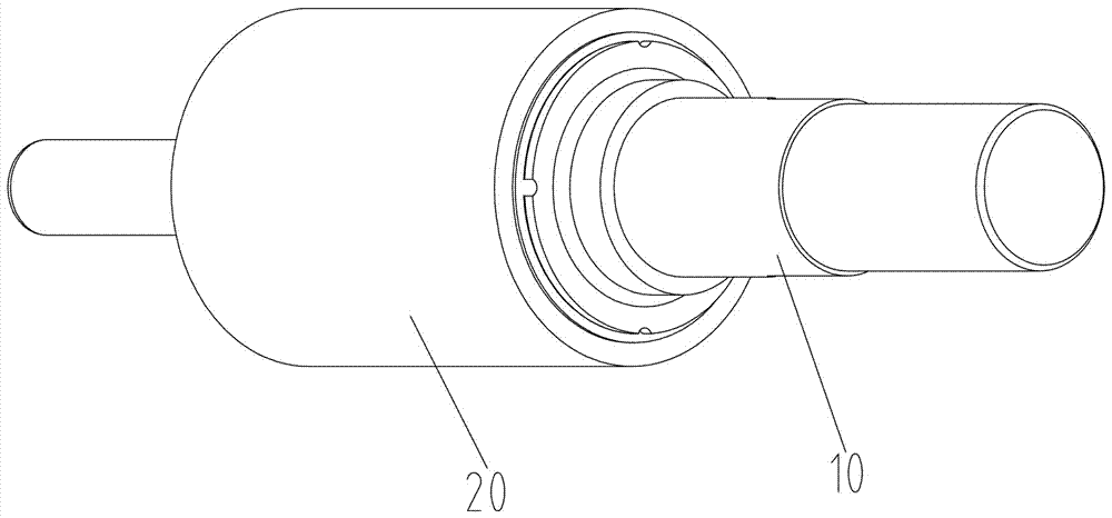
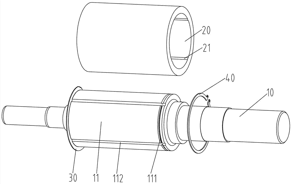
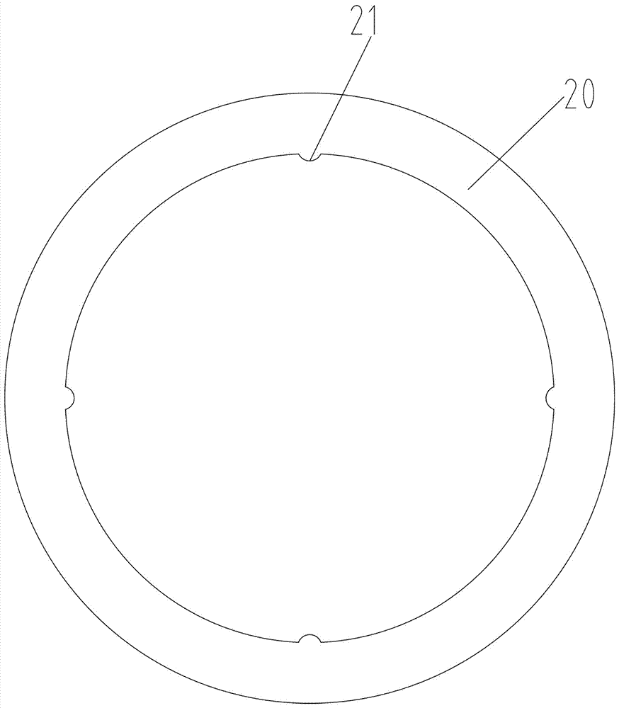
[0025] Such as figure 1 and figure 2 , The rotor proposed by the present invention includes a rotating shaft 10 and a magnetic ring 20 , the rotating shaft 10 is provided with a magnetic ring position 11 , and the magnetic ring 20 is sleeved on the magnetic ring position 11 of the rotating shaft 10 . The magnetic ring position 11 is provided with an axial limiting device, and the axial limiting device is used to limit the movement of the magnetic ring in the axial direction of the rotating shaft. A circumferential limiting structure is provided on the opposite surface of the magnetic ring and the magnetic ring, and the circumferential limiting structure is used to limit the rotation of the magnetic ring on the rotating shaft. In this way, the magnetic ring is fixed on the rotating shaft through the axial limiting device and the circumferential limiting structure, and the magnetic ring and the opposite surfaces of the magnetic ring can be bonded together.

[0026] The first ...


PUM

PropertyMeasurementUnit
Arc angleaaaaaaaaaa

Abstract

The invention discloses a rotor and a servo motor. The rotor comprises a rotating shaft and a magnet ring, the magnet ring sleeves at the magnet ring position of the rotating shaft, an axial limit device is arranged at the magnet ring position and limits the magnet ring to axially move on the rotating shaft, and a circumferential limit structure is arranged on the opposite surface of the magnet ring and the magnet ring position and limits the magnet ring to rotate on the rotating shaft. According to the rotor, the magnet ring is fixed on the rotating shaft through the axial limit device and the circumferential limit structure, glue is omitted, failure of the glue is avoided, the magnet ring still cannot move or fly off even if the surface temperature of the rotating shaft rises after the motor bears load or overload for a long time, and reliability of the motor is improved.

Description

technical field [0001] The invention relates to the technical field of motors, and more specifically relates to a rotor and a servo motor. Background technique [0002] The rotor is an important part of the motor, and its quality directly affects the performance of the motor. Due to the high control precision and good performance of the servo motor, it has higher requirements on the quality of the rotor. [0003] The traditional surface-mounted magnetic ring rotor structure uses glue to fix the permanent magnet magnetic ring on the surface of the shaft to prevent the permanent magnet magnetic ring from moving, but the use of glue bonding has the following disadvantages: [0004] 1. When the motor is under long-term load or overload, the surface temperature of the rotating shaft will rise, which will reduce the bonding performance of the glue, and there will be a risk of glue failure, causing the magnetic ring to move or even fly out, which may cause the motor to lose contro...

Claims


Application Information

Patent Timeline
IPC IPC(8): H02K1/27
CPCH02K1/2706
Inventor 王瑞东黄侠昌钟成堡肖胜宇李峰岩马艳娇
Owner ZHUHAI GREE REFRIGERATION TECH CENT OF ENERGY SAVING & ENVIRONMENTAL PROTECTION
Learn More