MMC sub-module with obstacle removal capability and current converter provided with sub-module

A technology of sub-modules and power electronic devices, applied in the direction of output power conversion device, AC power input conversion to DC power output, electrical components, etc., can solve the problem of sub-module structure coupling increasing system complexity and control difficulty, device triggering signal Consistency requirements are high, the number of switching tubes is large, etc., to achieve the effect of benefiting hardware cost, reducing the difficulty of research and development, and simple control

Inactive Publication Date: 2017-11-24
NORTH CHINA ELECTRIC POWER UNIV (BAODING)
View PDF0 Cites 4 Cited by
  • Summary
  • Abstract
  • Description
  • Claims
  • Application Information

AI Technical Summary

Problems solved by technology

The full-bridge sub-module has 4 switch tubes, which can output three levels of 0, +U, and -U, and -U is an unnecessary state in the actual application of MMC. The actual full-bridge sub-module is equivalent to a two-level sub-module. This sub-module can clear the fault current by blocking the pulse signal, but the number of switch tubes is large, and the consistency of the trigger signal of the device is high; the device of the clamping twin sub-module has 5 switch tubes, which can output 0, U, 2U three levels, compared with the full-bridge sub-module, the actual number of available levels of the sub-module device is increased, and the number of devices is significantly reduced, but the coupling of the sub-module structure increases the complexity of the system and the difficulty of control

Method used


Image

  • MMC sub-module with obstacle removal capability and current converter provided with sub-module
  • MMC sub-module with obstacle removal capability and current converter provided with sub-module
  • MMC sub-module with obstacle removal capability and current converter provided with sub-module

Examples


Embodiment Construction

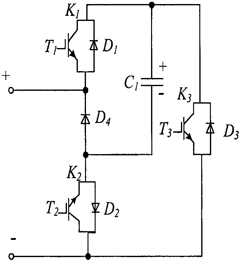
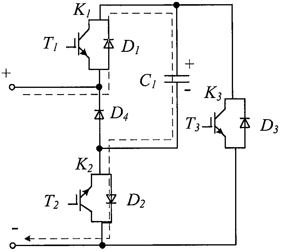
[0025] A MMC sub-module with obstacle clearance capability of the present invention will be described in detail below with reference to the embodiments and the accompanying drawings.

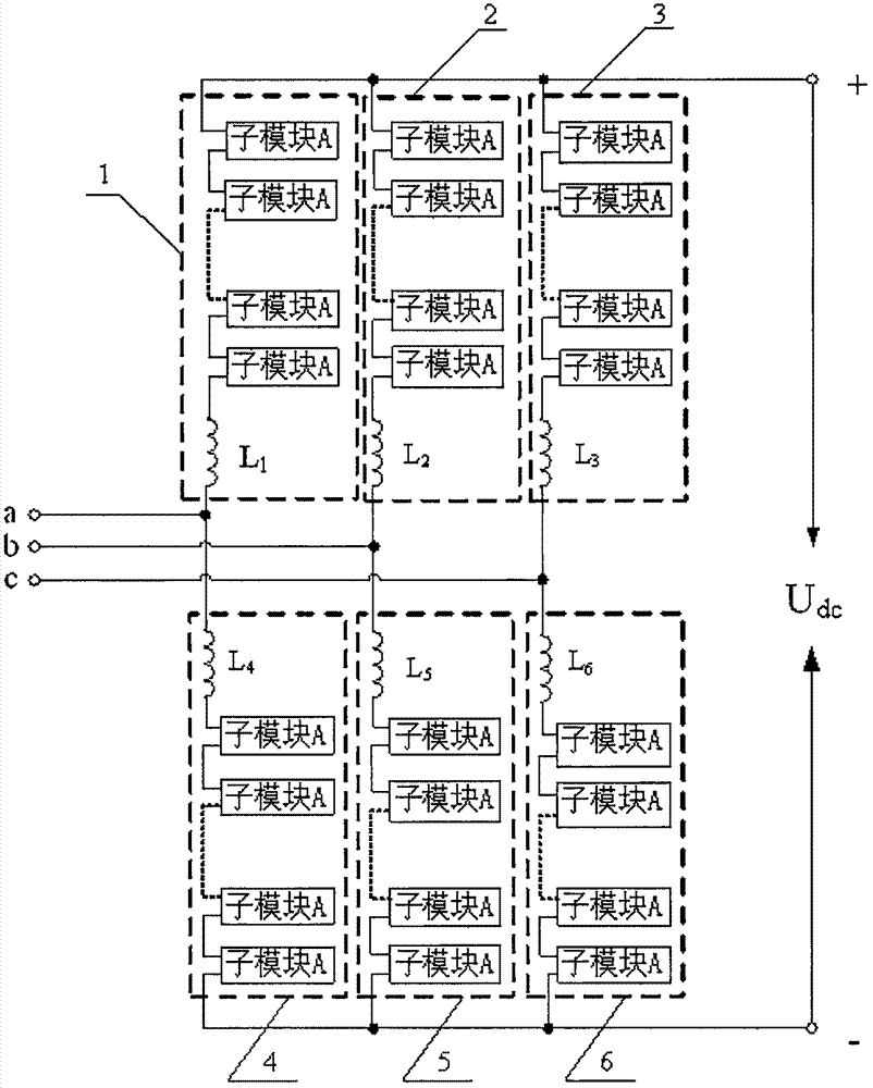
[0026] like figure 1 As shown in the figure, an MMC sub-module with obstacle clearance capability of the present invention includes a first switch K connected in series in sequence 1 , the fourth diode D 4 and the second switch K 2 , the first switch K 1 Connect the other end of the first capacitor C 1 one end and the third switch K 3 one end of the second switch K 2 with the fourth diode D 4 The connected intersection point connects the first capacitor C 1 the other end of the second switch K 2 The other end is connected to the third switch K 3 the other end of the first switch K 1 with the fourth diode D 4 The connected intersections constitute the positive poles of the MMC sub-modules with the barrier-clearing capability, and the second switch K 2 with the third switch K 3 The co...


PUM


Abstract

The present invention provides an MMC sub-module capable of clearing obstacles and a converter having the sub-module. The MMC sub-module capable of clearing obstacles of the present invention mainly includes: 3 switch units, 1 diode and 1 capacitor, wherein The structure of the switch unit is the same, which is composed of a fully-controlled power electronic device and a diode in antiparallel connection; the structure of the converter with the ability to clear obstacles is a symmetrical three-phase structure, and the upper and lower bridges of each phase The arms are composed of more than two MMC sub-modules with obstacle-clearing capabilities connected in series with inductors. The MMC sub-module with the ability to remove obstacles and the converter device with the sub-module of the present invention have a small number and simple control, and can quickly clear the fault current when a unipolar short-circuit fault or a bipolar short-circuit fault occurs on the DC side, and It can realize fast restart under instantaneous fault, effectively guaranteeing the stable operation of the system.

Description

technical field [0001] The present invention relates to an MMC submodule. In particular, it relates to an MMC sub-module with obstacle clearance capability and a converter with the sub-module. Background technique [0002] Modular multi-level converters have received extensive attention at home and abroad since they were proposed by R.Marquardt and A.Lesnicar of the University of Bundeswehr Munich in Germany in 2002, and have now become the preferred converters in HVDC transmission projects. Compared with traditional voltage source converters, MMC has the following advantages: [0003] (1) The modular structure is easy to expand, and enough sub-modules can be set to meet the needs of different voltages and power levels; [0004] (2) Redundant sub-modules enable the system to have better fault handling capability and reliability; [0005] (3) The output waveform quality is high and the harmonic content is low. [0006] Since the DC system has no current zero-crossing poin...

Claims


Application Information

Patent Timeline
IPC IPC(8): H02M7/483H02H7/122H02H7/26
CPCH02M7/483H02H7/1227H02H7/268
Inventor 孟明苏亚慧
Owner NORTH CHINA ELECTRIC POWER UNIV (BAODING)
Why Eureka
Try Eureka