Mini-type acoustical generator

A sounder and micro technology, applied in the direction of fixing/tensioning of sensors, electrical components, diaphragms, etc., can solve the problem that it cannot be installed on the side wall of the casing, but can only be set at the bottom of the micro sounder, the micro sounder Unable to meet the problems of portable electronic equipment and micro sounder leaving airflow and other problems, to achieve the effect of expansion performance, good sealing and high waterproof performance

Pending Publication Date: 2017-11-24
GOERTEK INC
View PDF4 Cites 8 Cited by
  • Summary
  • Abstract
  • Description
  • Claims
  • Application Information

AI Technical Summary

Problems solved by technology

[0003] At present, the rear sound hole of the micro sounder is integrated with the shell, which is difficult to realize when the shell is injection molded, and sometimes a slider structure must be used; Blocking, it can only be crafted from the front (front cover) of the micro-sounder, which has certain limitations
At the same time, with the improvement of the waterproof performance requirements of the micro-speaker, it is necessary to set the outlet groove of the lead wire of the voice coil at the lower end of the casing. This structure requires a lead wire between the casing and the side wall of the yoke. As a result, the rear sound hole of the micro-sounder cannot be set on the side wall of the shell, but can only be set at the bottom of the micro-sounder, which requires portable electronic devices to leave a space for airflow to the micro-sounder in height However, with the continuous thinning of portable electronic devices, it is no longer possible to leave space for the airflow of the micro-sounder in height. Therefore, the micro-sounder with this structure cannot meet the needs of portable electronic devices.

Method used


Image

  • Mini-type acoustical generator
  • Mini-type acoustical generator
  • Mini-type acoustical generator

Examples


Embodiment Construction

[0033] Below in conjunction with accompanying drawing and embodiment, further elaborate the present invention.

[0034] The inner refers to the position close to the center of the micro-sounder, and the outer refers to the position away from the center of the micro-sounder; the direction "up" refers to the direction where the vibration system is installed, and the direction "down" refers to the direction where the magnetic circuit is installed. system orientation.

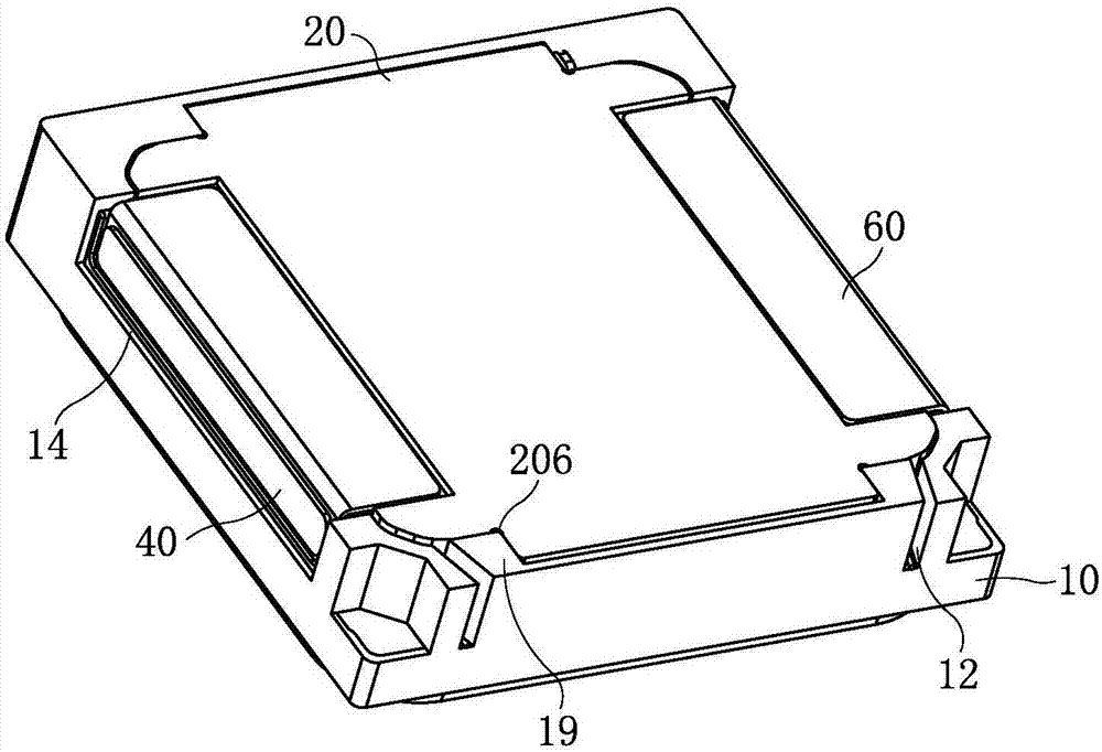
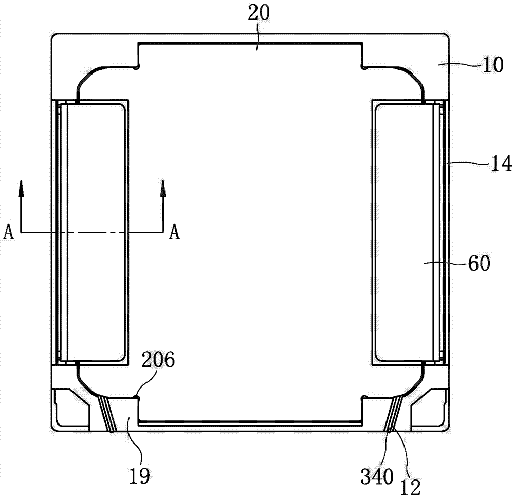
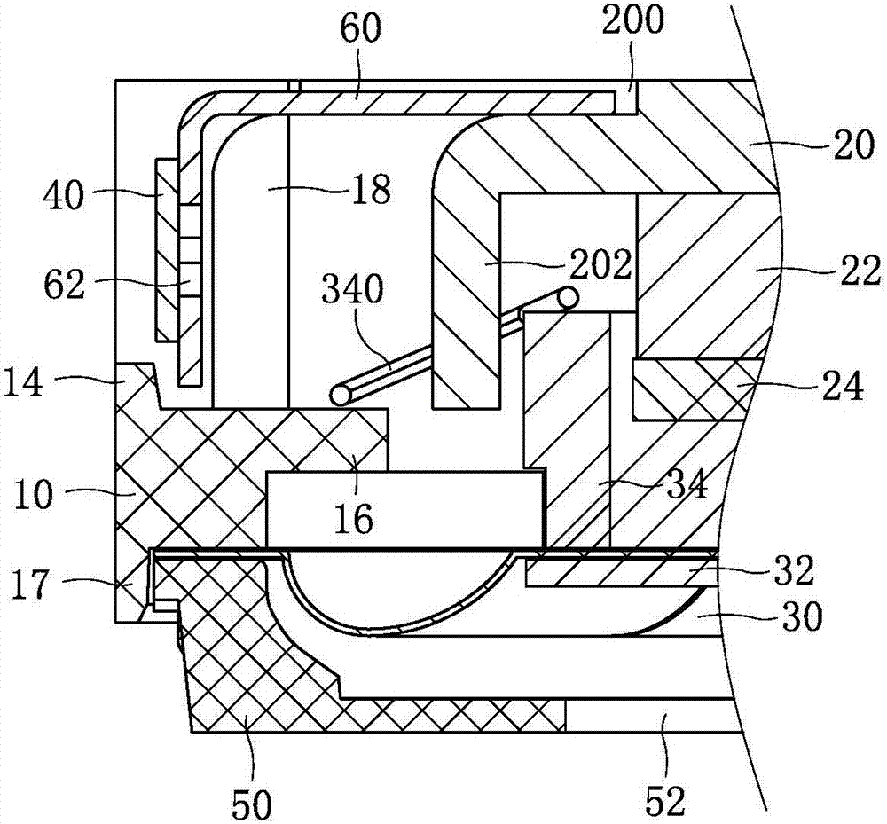
[0035] like figure 1 , figure 2 , image 3 and Figure 7 As shown together, a miniature sound generator includes a ring-shaped casing 10 , the casing 10 has a square structure, and a front cover 50 is combined at the upper end of the casing 10 . A vibration system and a magnetic circuit system are accommodated in the space jointly enclosed by the casing 10 and the front cover 50 . The vibration system includes a diaphragm 30 and a voice coil 34, the edge of the diaphragm 30 is fixed between the upper end surf...


PUM


Abstract

The invention discloses a mini-type acoustical generator and relates to the technical field of electroacoustic products. The mini-type acoustical generator comprises a shell, a vibrating system and a magnetic circuit system, wherein the vibrating system and the magnetic circuit system are contained in the shell. The magnetic circuit system comprises a magnet yoke installed on the shell, and the vibrating system comprises a vibrating diaphragm and a voice coil. A rear sound aperture of the mini-type acoustical generator is formed in the lateral side of the mini-type acoustical generator, the part, corresponding to the rear sound aperture side, of the shell and the magnet yoke are sealed by using a metal sheet, one part of the metal sheet is combined with the magnet yoke in a sealed mode, and the other part of the metal sheet is combined with the shell in a sealed mode. The rear sound aperture is formed in the metal sheet. By means of the mini-type acoustical generator, the technical problem that in the prior art, a mini-type acoustical generator with the rear sound aperture in the lateral side has limitations is solved; in the mini-type acoustical generator, the performance is expanded, the mini-type acoustical generator is simple in assembly, meanwhile, good in water proof performance, long in service life and capable of meeting the requirements for thinning development of portable electronic equipment.

Description

technical field [0001] The invention relates to the technical field of electroacoustic products, in particular to a miniature sound generator. Background technique [0002] Miniature sound generator is an important acoustic component of portable electronic equipment, which is used to complete the conversion between electrical signals and sound signals, and is an energy conversion device. The micro sounder usually includes a shell and a front cover, and a vibration system and a magnetic circuit system housed in the space enclosed by the shell and the front cover. The magnetic circuit system includes a yoke, and the center of the yoke is fixed with a magnet and a magnetic plate in turn. There is a side wall of the yoke on the edge of the yoke, and a magnetic gap is set between the magnet and the magnetic plate and the side wall of the yoke; the vibration system includes a diaphragm and a voice coil, and the voice coil works in the magnetic gap of the magnetic circuit system. ...

Claims


Application Information

Patent Timeline
Patent Type & Authority Applications(China)
IPC IPC(8): H04R9/06H04R9/02H04R7/18
CPCH04R7/18H04R9/02H04R9/06
Inventor 刘华伟
Owner GOERTEK INC
Why Eureka
Try Eureka