A linear constant current drive circuit

A linear constant current drive and circuit technology, applied in electric light sources, electrical components, electroluminescent light sources, etc., can solve problems such as high power factor and low harmonic distortion, achieve high power factor, low harmonic distortion, avoid The effect of LED overcurrent operation

Active Publication Date: 2019-01-18
SHANGHAI LOOALL ELECTRONICS CO LTD
View PDF3 Cites 0 Cited by
  • Summary
  • Abstract
  • Description
  • Claims
  • Application Information

AI Technical Summary

Problems solved by technology

[0005] The invention provides a linear constant current drive circuit, which can realize higher power factor and lower harmonic distortion, overcome the defects of the above-mentioned technologies, and solve the existing technical problems

Method used


Image

  • A linear constant current drive circuit
  • A linear constant current drive circuit
  • A linear constant current drive circuit

Examples


Embodiment 1

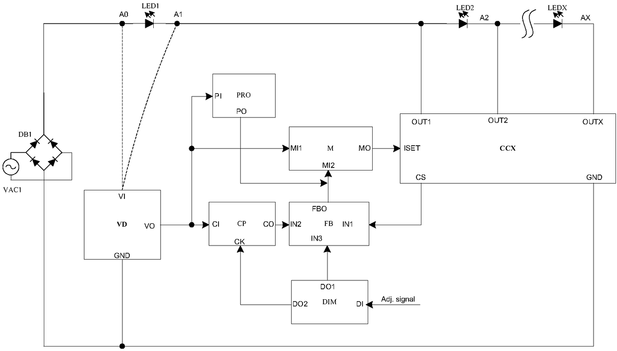
[0037] figure 1 It is a schematic diagram of the principle of the linear constant current drive circuit of the first embodiment.

[0038] Such as figure 1 As shown, LED1, LED2, and LEDX are connected in series in sequence to form a load, forming an anode node A0 and several cathode nodes A1, A2, and AX. The input terminal of the rectifier bridge DB1 is connected to the mains VAC1, and the output positive pole is connected to the anode node A0. The negative pole is grounded, and the drive circuit includes: switching constant current source CCX, voltage detection circuit VD, feedback circuit FB, multiplier M, constant power compensation circuit CP, protection circuit PRO and dimming circuit DIM.

[0039] The switching constant current source CCX includes a current setting terminal ISET for setting the current of the switching constant current source, a common ground GND, a current detection terminal CS for responding to switching the constant current source current, and several...

Embodiment 2

[0082] In the second embodiment, except that the structure of the protection circuit PRO is different from that of the first embodiment, other circuit structures and working principles are the same, and will not be described again.

[0083] Figure 8 It is a circuit diagram of the protection circuit PRO of the second embodiment.

[0084] Such as Figure 8 As shown, the protection circuit PRO includes a filter F8, an amplifier AMP8 and a transistor Q8. The input terminal of the filter F8 is connected to the input terminal PI of the protection circuit PRO, the output terminal is connected to the inverting input terminal of the amplifier AMP8, the output terminal of the amplifier AMP8 is connected to the gate of the transistor Q8, the source of the transistor Q8 is grounded, and the amplifier Both the non-inverting input terminal of AMP8 and the drain of transistor Q8 are connected to the output terminal PO of the protection circuit PRO.

[0085] The input terminal PI of the p...

Embodiment 3

[0087] In the third embodiment, except that the structure of switching the constant current source CCX is different from that of the first embodiment, other circuit structures and working principles are the same, and will not be described again.

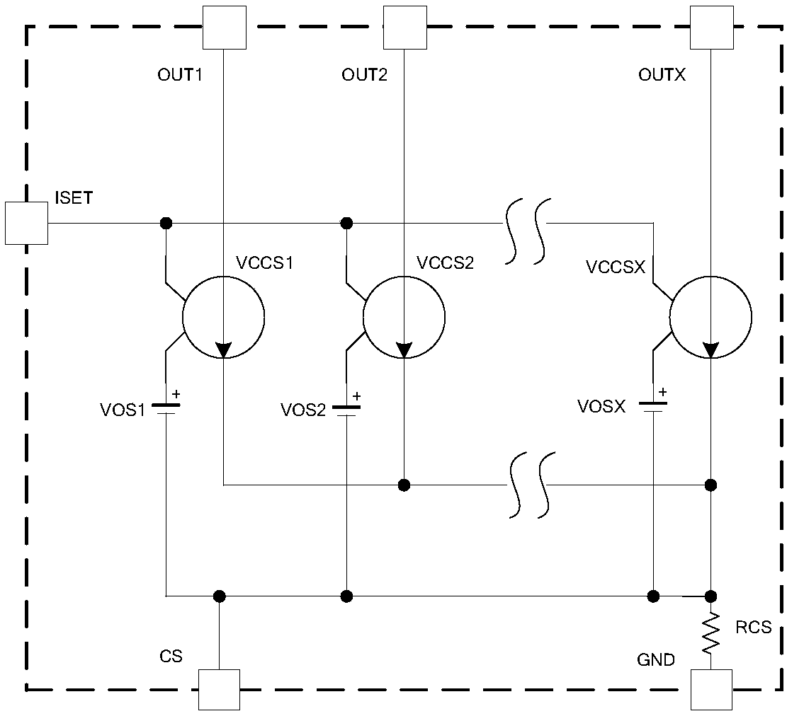
[0088] Figure 9 It is the circuit diagram of the switching constant current source CCX of the third embodiment.

[0089] Such as Figure 9 As shown, will figure 2 The second control terminal of each voltage-controlled current source in the switching constant current source CCX circuit shown is respectively connected to one end of several signal bias sources VOS1, VOS2 and VOSX, and several signal bias sources VOS1, VOS2 and VOSX The other ends of are connected to the current setting terminal ISET, then can realize and figure 2 same function.


PUM


Abstract

The invention provides a linear constant current drive circuit, which is powered by the mains VAC1 through the rectifier bridge DB1, and the load is a plurality of LEDs connected in series to form an anode node and a plurality of LED cathode nodes; the input end of the rectifier bridge DB1 is connected to the mains VAC1 connected, the output positive pole is connected to the anode node; it includes a switching constant current source CCX, a voltage detection circuit VD, a feedback circuit FB and a multiplier M. Its advantage is that it can make the mains current waveform close to a sine wave; when the effective value of the mains voltage is low, the current flowing through the LED is reduced to avoid the LED over-current operation; The constant power mode gradually transitions to the constant current mode, and the constant current mode improves the LED brightness variation caused by power grid fluctuations in low brightness applications.

Description

technical field [0001] The invention relates to a linear drive circuit, in particular to a linear constant current LED drive circuit and an integrated circuit designed using the same, which is suitable for LED lighting applications. Background technique [0002] At present, LED lamps have been widely used in lighting applications in various fields. LEDs cannot be directly connected to AC power, and need to be equipped with a corresponding current-limiting drive device. The current LED drive scheme is mainly based on traditional high-frequency switching power supplies. This scheme requires high-frequency switching circuits, complex circuits, high cost, and linear constant current drive. It is a development trend that the scheme replaces the switching power supply scheme. [0003] The input current waveforms of linear constant current drive schemes on the market are all pulse waves, square waves or ladder waveforms, which show low power factor and large harmonic distortion. T...

Claims


Application Information

Patent Timeline
Patent Type & Authority Patents(China)
IPC IPC(8): H05B33/08H05B44/00
CPCH05B45/10Y02B20/30H05B45/395H05B47/25
Inventor 邵藴奇
Owner SHANGHAI LOOALL ELECTRONICS CO LTD
Why Eureka
Try Eureka