Chain type die clamping device

A mold clamp, chain-type technology, applied in presses, metal processing equipment, forming tools, etc., can solve the problems of unusable molds and occupying space.

Inactive Publication Date: 2017-11-28
苏州格莱富机械科技有限公司
View PDF0 Cites 2 Cited by
  • Summary
  • Abstract
  • Description
  • Claims
  • Application Information

AI Technical Summary

Problems solved by technology

[0002] At present, in the quick mold change industry of punch presses, self-propelled clamps are fixed on the punch presses to clamp the molds on the punch presses. The self-propelled clamps currently used are in the form of cylinder push-pull, but such a method As a result, the cylinder needs to be installed on the table of the punching machine, occupying a large space range, resulting in the unusable size of the mold

Method used


Image

  • Chain type die clamping device
  • Chain type die clamping device
  • Chain type die clamping device

Examples


Embodiment Construction

[0012] The present invention will be further described below in conjunction with the accompanying drawings and specific embodiments.

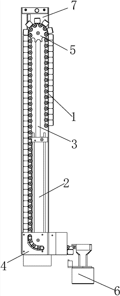
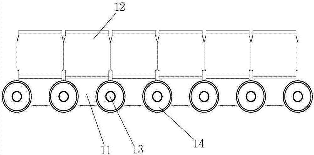
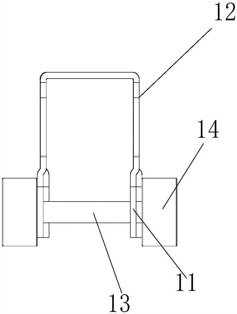
[0013] Such as figure 1 The shown chain mold clamp includes a cylinder, and the cylinder includes a cylinder body 2 and a piston rod 3 arranged in the cylinder body 2, and also includes a chain guide seat 4, a chain 1, a sprocket 5 and a mold clamp 6, The bottom of the cylinder body 2 is fixed on the chain guide seat 4 by fasteners such as bolts or screws, and the inside of the chain guide seat 4 is provided with an arc-shaped slot for guiding the movement track of the chain 1, and one end of the chain 1 protrudes in an arc-shaped The through groove is fixedly connected to the mold clamp 6 by fasteners such as bolts or screws, and the other end of the chain 1 is fixedly connected to the cylinder body 2 by bypassing the piston rod 3 by fasteners such as bolts or screws. The sprocket 5 Fixed on the head of the piston rod 3, the sprocket 5 is eng...


PUM


Abstract

The invention discloses a chain clamp, which comprises a cylinder, the cylinder includes a cylinder body and a piston rod arranged in the cylinder body, and also includes a chain guide seat, a chain, a sprocket and a mold clamp, and the bottom of the cylinder body is fixed On the chain guide seat, there is an arc-shaped slot to guide the movement track of the chain inside the chain guide seat. One end of the chain protrudes from the arc-shaped slot and is fixedly connected with the clamp, and the other end of the chain goes around the piston rod. It is fixedly connected with the cylinder body, the sprocket is fixed on the head of the piston rod, and the sprocket is engaged with the chain. The chain guide seat of the chain clamp of the present invention is fixed on the edge of the table of the punch press, and through the vertical movement of the chain , driving the clamp to move horizontally can achieve the effect of pushing and pulling the clamp to the edge of the mold. At the same time, the chain drive part of the chain clamp is installed outside the side of the punch press, so that the chain drive of the chain clamp It does not occupy the space of the punch table, so it does not affect the use of large molds.

Description

technical field [0001] The invention relates to a die clamp for a punch press, in particular to a chain type clamp. Background technique [0002] At present, in the quick mold change industry of punch presses, self-propelled clamps are fixed on the punch presses to clamp the molds on the punch presses. The self-propelled clamps currently used are in the form of cylinder push-pull, but such a method The cylinder needs to be installed on the table top of the punch press, which takes up a lot of space and makes it impossible to use larger molds. Contents of the invention [0003] The technical problem solved by the invention is to provide a chain clamp that does not occupy the space on the punch table and does not affect the use of large molds. [0004] The technical solution adopted by the present invention to solve the technical problem is: the chain mold clamp includes a cylinder, the cylinder includes a cylinder body and a piston rod arranged in the cylinder body, and al...

Claims


Application Information

Patent Timeline
Patent Type & Authority Applications(China)
IPC IPC(8): B21D37/14B30B15/02
CPCB21D37/14B30B15/02
Inventor 管高峰田进
Owner 苏州格莱富机械科技有限公司
Why Eureka
Try Eureka