Method for assembling frame assemblies

An assembly method and frame technology, applied in assembly machines, metal processing equipment, manufacturing tools, etc., can solve the problems of high assembly cost, low quality stability, poor efficiency, etc. The effect of assembly efficiency

Active Publication Date: 2017-11-28
黑龙江义荣制药机械有限公司
View PDF17 Cites 13 Cited by
  • Summary
  • Abstract
  • Description
  • Claims
  • Application Information

AI Technical Summary

Problems solved by technology

The efficiency of this assembly method is poor, the quality stability of the assembly is low, and the assembly cost is too high

Method used


Image

  • Method for assembling frame assemblies
  • Method for assembling frame assemblies
  • Method for assembling frame assemblies

Examples


Embodiment 2

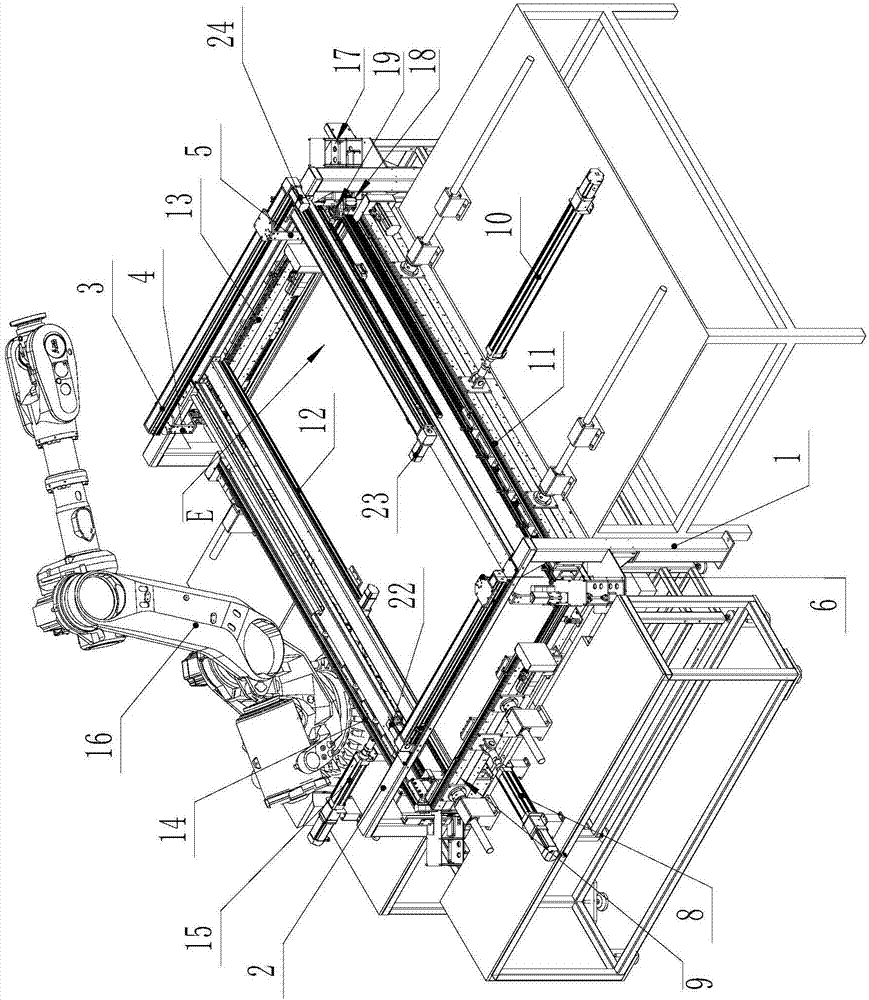
[0018] figure 1 It is a perspective view of the structure of the automatic framing device of Embodiment 2 of the present invention;

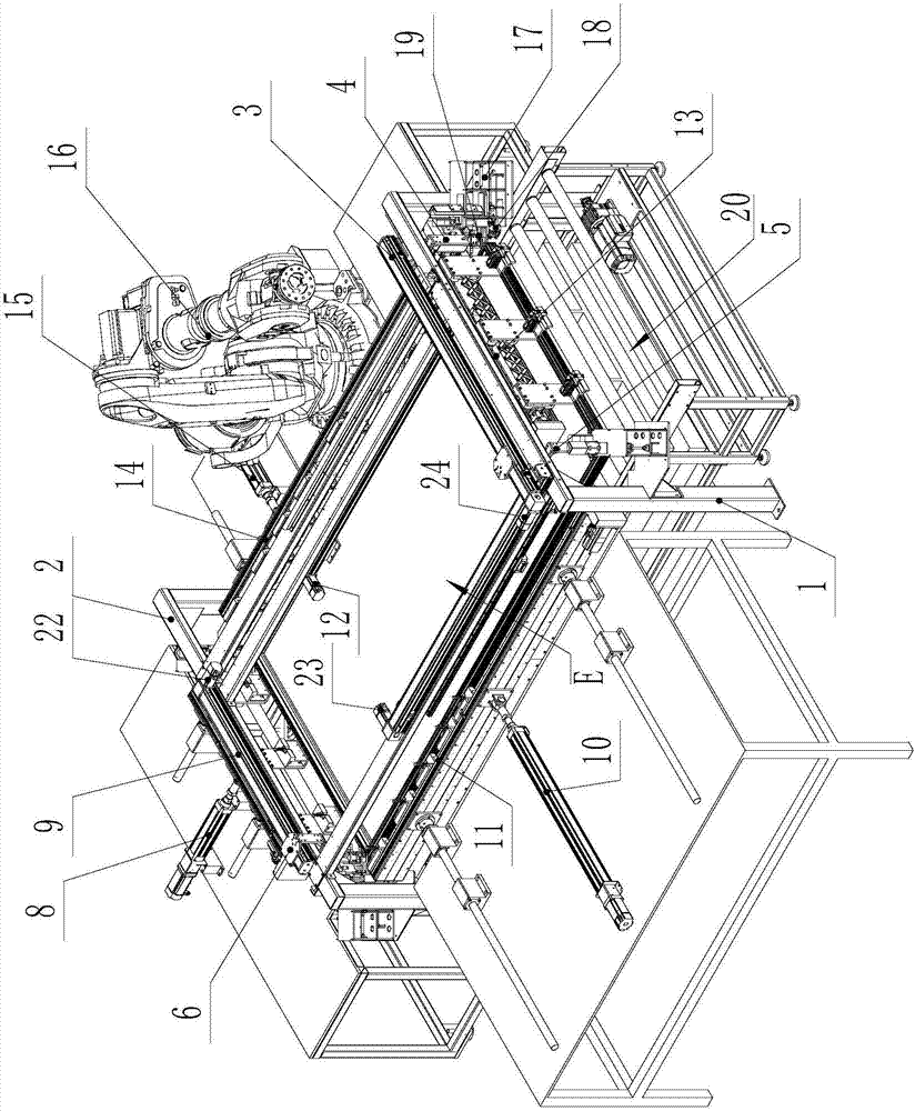
[0019] figure 2 It is a perspective view of another angle of the automatic framing device of Embodiment 2 of the present invention;

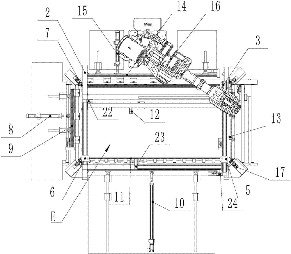
[0020] image 3 It is a top view of the automatic framing device of Embodiment 2 of the present invention;

[0021] Figure 4 It is a three-dimensional view of the structure of the components driving the action of the frame in Embodiment 2 of the present invention;

[0022] Figure 5 It is a top view of the components driving the action of the frame in Embodiment 2 of the present invention;

[0023] Figure 6 It is the structural diagram of the left frame clamping device of Embodiment 2 of the present invention;

[0024] Figure 7 It is the structural diagram of the right frame clamping device of Embodiment 2 of the present invention;

[0025] Figure 8 It is the side structural diagram when the right ...

Embodiment 1

[0053] This embodiment discloses a frame component assembly method, which defines a rectangular assembly area, corner brackets are set near each right angle of the assembly area, and the right-angle plate part of the corner bracket is connected to the right-angle side of the assembly area Correspondingly parallel; the left frame, right frame, front frame and rear frame are placed around the assembly area, and the two ends of each frame are complementary 45° mating surfaces; the height of the frame and corner code meets the assembly requirements, and the left frame faces The right and right frames move to the left, the front frame moves backward, and the rear frame moves forward synchronously. During the movement of each frame, the 45° mating surface at both ends of each frame first contacts with the corresponding right-angle plate part of the corner code so that the right-angle plate part enters When the frames continue to move, the corner brackets are driven to move to the cen...


PUM


Abstract

The invention discloses a method for assembling frame assemblies. The method includes defining a rectangular assembling region and arranging corners near each right angle of the assembling region; placing a left frame, a right frame, a front frame and a rear frame on the periphery of the assembling region; allowing the heights of the frames and the corners to meet assembling requirements, synchronously shifting the left frame rightwards, the right frame leftwards, the front frame rearwards and the rear frame forwards, allowing 45-degree matched surfaces at two ends of each frame to be in contact with corresponding right angle plates of the corresponding corner in shifting procedures of the various frames, then extending the corresponding right angle plates into ports of two ends of each insertion hole of the corresponding frame, then driving the corners to move towards the center of the assembling region when the various frames continue to be shifted, and completely inserting the right angle plates of the corners into the holes of the corresponding frames when the 45-degree matched surfaces of the adjacent frames are in contact with one another so as to completely assemble each frame assembly. The corresponding complementary 45-degree matched surfaces are arranged at the two ends of each frame. The method has the advantages that the four frames and the corners can be assembled by the aid of the method at one step, and accordingly the assembling efficiency can be improved.

Description

technical field [0001] The invention relates to an assembly method, in particular to an assembly method of a frame assembly. Background technique [0002] The frame assembly generally includes four frames, the two ends of the frame are complementary 45° slopes, and the four frames are assembled into a rectangular frame assembly through corner codes. The frame assembly can be applied in many technical fields, such as the frame assembly of doors and windows. In addition to the frame and corners, some frame components also have the assembly of the bottom plate, that is, there are bottom plate slots on the frame, and the bottom plate, frame and corners need to be assembled, and this frame component can be used in the frame of solar collectors. on the component. [0003] The solar collector mainly includes a heat absorbing plate, a glass plate, an insulating cotton layer, a bottom plate frame assembly and a core tube assembly. When these components of the solar collector are as...

Claims


Application Information

Patent Timeline
Patent Type & Authority Applications(China)
IPC IPC(8): B23P21/00
CPCB23P21/002
Inventor 赵亮
Owner 黑龙江义荣制药机械有限公司
Why Eureka
Try Eureka