Optical super-resolution imaging system based on inverted microscope and micro-sphere lens and dynamic imaging method using same

An inverted microscope and super-resolution technology, applied in the field of optical super-resolution imaging systems, can solve the problem of not being able to be captured and imaged by an objective lens, and achieve the effects of expanding nano-observation imaging and nano-manipulation capabilities, and improving efficiency and success rate.

Inactive Publication Date: 2017-11-28
苏州显纳精密仪器有限公司
View PDF5 Cites 9 Cited by
  • Summary
  • Abstract
  • Description
  • Claims
  • Application Information

AI Technical Summary

Problems solved by technology

Under an upright microscope, these transformed propagating waves are captured and imaged by the objective lens; while under an inverted microscope, these transformed propagating waves are far away from the objective lens of the microscope, so they cannot be collected and imaged by the objective lens

Method used


Image

  • Optical super-resolution imaging system based on inverted microscope and micro-sphere lens and dynamic imaging method using same
  • Optical super-resolution imaging system based on inverted microscope and micro-sphere lens and dynamic imaging method using same
  • Optical super-resolution imaging system based on inverted microscope and micro-sphere lens and dynamic imaging method using same

Examples


Embodiment Construction

[0023] Below in conjunction with accompanying drawing, describe in detail a kind of optical super-resolution imaging system based on inverted microscope and microsphere lens of the present invention and the specific embodiment of the dynamic imaging method that adopts this system:

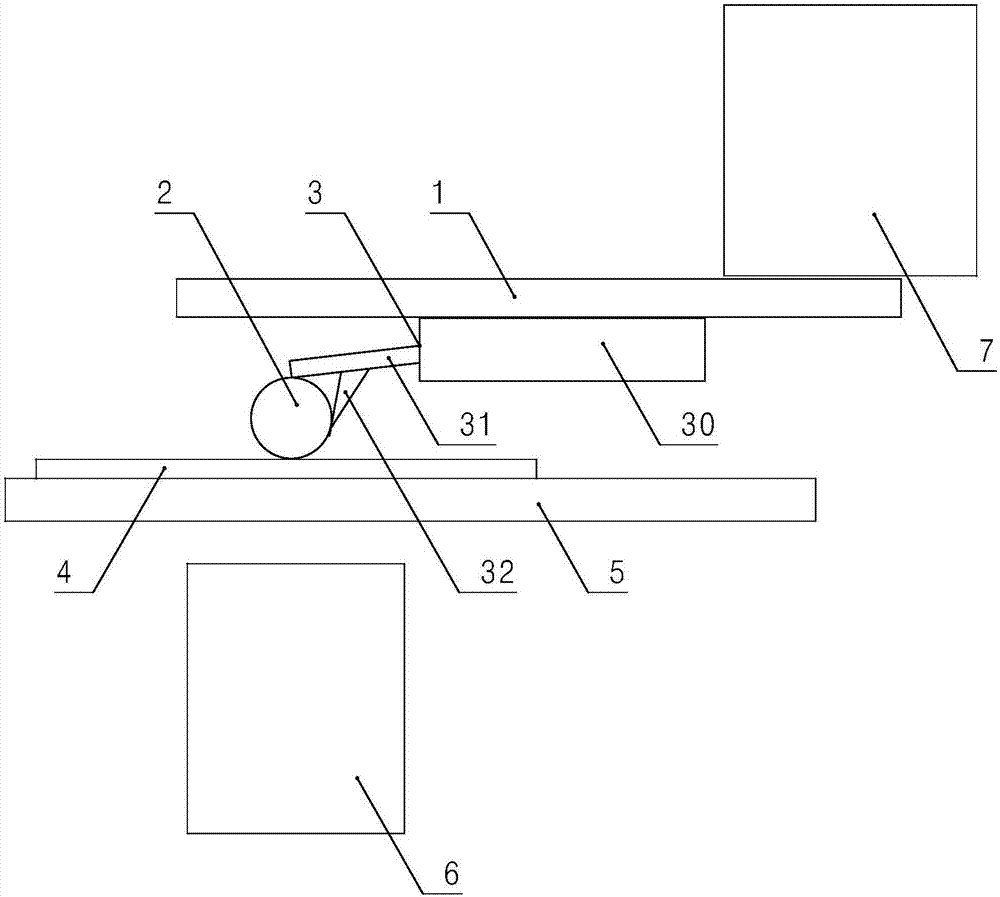
[0024] Such as figure 1 As shown, an optical super-resolution imaging system based on an inverted microscope and a microsphere lens according to the present invention includes: optical reflective ytterbium 1, microsphere lens 2, atomic force microscope scanning probe 3, sample stage 5, optical inversion The microscope 6 and the displacement stage 7 capable of three-dimensional precision movement, the specific structure of the atomic force microscope scanning probe 3 includes: a base 30, a cantilever 31 arranged on the base 30, and a needle tip 32 arranged on the cantilever 31 The base 30 of the atomic force microscope scanning probe 3 is pasted on the described optical mirror 1, and the described m...


PUM


Abstract

The invention discloses an optical super-resolution imaging system based on an inverted microscope and a micro-sphere lens which can realize optical super-resolution imaging under an inverted microscope. The optical super-resolution imaging system includes an optical mirror, a micro-sphere lens, an atomic force microscope scanning probe, a sample stage, an optical inverted microscope, and a displacement stage. The atomic force microscope scanning probe is pasted through a substrate thereof onto the optical mirror. The micro-sphere lens is fixed to a cantilever beam and a tip of the atomic force microscope scanning probe, and is positioned below the optical mirror. The optical mirror is fixed to the displacement stage above the optical mirror. The sample stage is positioned below the micro-sphere lens. The optical inverted microscope is positioned below the sample stage, and the objective lens of the optical inverted microscope is positioned right below the micro-sphere lens. The invention further provides a dynamic imaging method using the system. The system of the invention is especially suitable for observing the internal structure of living cells and other occasions.

Description

technical field [0001] The invention relates to an optical super-resolution imaging system and method based on an inverted microscope and a microsphere lens. Specifically, the optical super-resolution microscopic observation and imaging under an inverted microscope is realized by using the control mechanism of a displacement stage, and macro, micro, and nano imaging can be realized. Seamless observation, and nanomanipulation with real-time visual feedback. It is mainly used in fields that require nanoscale super-resolution real-time dynamic observation and operation, including materials, life sciences and other fields. Background technique [0002] At the end of the 19th century, the German scientist Ernst Abbe defined the resolution of the optical microscope, which was considered to be half the wavelength of light, that is, about 0.2 microns, which is the famous optical diffraction limit. Thus, for most of the 20th century, scientists believed that optical microscopy would...

Claims


Application Information

Patent Timeline
Patent Type & Authority Applications(China)
IPC IPC(8): G02B21/00G02B21/02G02B27/58
CPCG02B21/0088G02B21/02G02B27/58
Inventor 李广勇刘振勇
Owner 苏州显纳精密仪器有限公司
Why Eureka
Try Eureka