
Energy buffer device for an aircraft

Inactive Publication Date: 2013-02-05
AIRBUS OPERATIONS GMBH
View PDF40 Cites 0 Cited by
  • Summary
  • Abstract
  • Description
  • Claims
  • Application Information

AI Technical Summary

Benefits of technology

The patent is aimed at providing a reliable and effective energy supply for aircrafts. The technical effect is to ensure the aircraft has a steady and consistent energy supply for its various systems.

Problems solved by technology

As a result of this, disadvantageously, non-used overcapacity is taken into account in the planning of such electrical systems for aircraft, as a result of which the costs of producing an aircraft increase.
While dividing these electrical devices into priority classes in dimensioning the current distribution systems makes it possible to work out the concurrent use of certain device classes, it does however not prevent dimensioning occurring on the basis of the peak-load requirement of the individual devices.
If the allocation of such devices, for example, takes place by means of the above-mentioned priority classes, it may not be possible to activate a consumer when required, because its activation is not provided for in this particular flight phase.

Method used


Image

  • Energy buffer device for an aircraft
  • Energy buffer device for an aircraft

Examples


Embodiment Construction

[0038]The examples described and drawings rendered are illustrative and are not to be read as limiting the scope of the invention as it is defined by the appended claims.

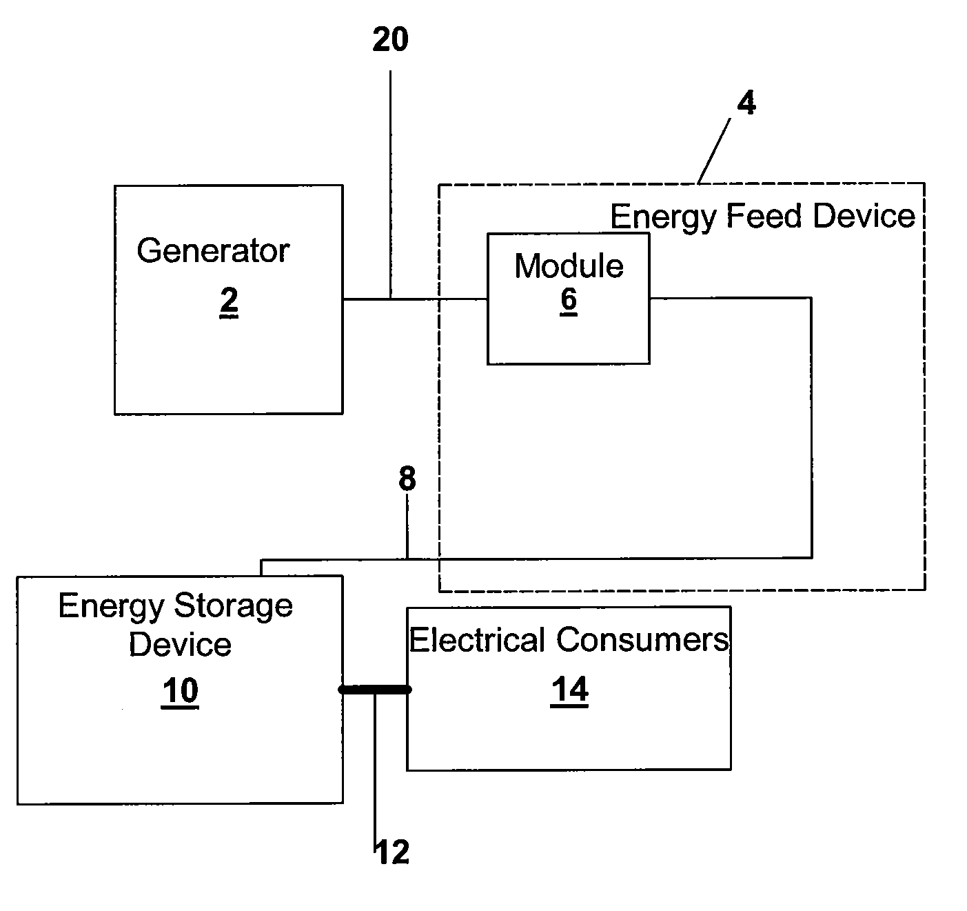
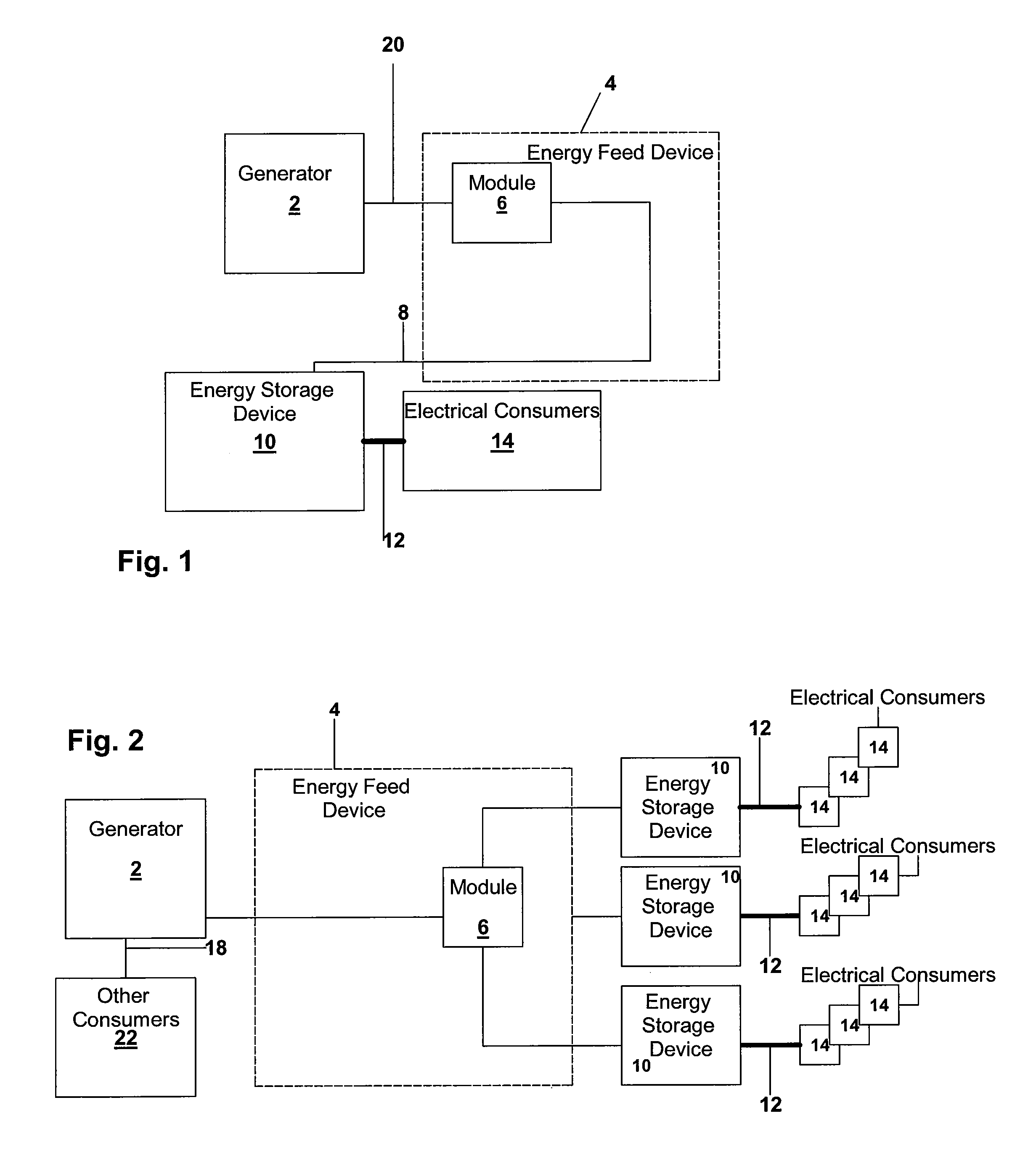
[0039]FIG. 1 shows a block diagram of an embodiment of an electrical system for an aircraft. The Figure shows a generator 2 that supplies power to an electrical consumer 14. For a short period of time, high power 12 Pout is to be supplied to the electrical consumer 14. In FIG. 1, this high power is indicated by a bold arrow 12. Corresponding to the high power 12 to be provided to the consumer 14, the associated energy supply unit is also to be designed to handle the increased power.

[0040]In one example, the electrical consumer 14, is a lift drive for a trolley lift or a lift drive for hat-rack bins. The hat-rack bins are, for example, overhead bins in the passenger compartment. To facilitate the stowing of baggage, the hat-rack bins may be lowered to approximately eye-level of passengers by means of a lift drive. Af...


PUM


Abstract

An energy buffer device supplies energy to a consumer in an aircraft, and an electrical system for an aircraft. In one example, the device includes an energy feed device, an energy storage device and an energy supply device. The energy supply device may have line with a larger cross-sectional area than a corresponding line of the energy feed device. With the use of an energy buffer device, power may be switched on only for a short period of time. In addition, in case of a voltage breakdown in an on-board network, energy may be stored in an energy storage device. Supply of energy may thus occur over a short time at correspondingly high power, without placing a load on an on-board network or a generator.

Description

RELATED APPLICATIONS[0001]This application claims the benefit of the filing date of U.S. Provisional Patent Application No. 60 / 644,914 filed Jan. 19, 2005 and of the German Patent Application No. 10 2005 002 545.5 filed Jan. 19, 2005, the disclosures of which are hereby incorporated herein by reference.FIELD OF THE INVENTION[0002]The field relates to the energy supply in an aircraft. In particular, the field relates to an energy buffer device for supplying energy to consumers in an aircraft. Furthermore, the field relates to an electrical system for an aircraft, and the use of a power capacitor.BACKGROUND[0003]When dimensioning generators, current distributors and electrical lines in aircraft engineering, today dimensioning is predominantly according to the maximum current-power requirement of the connected electrical consumers. This means that generators for the supply of current to the aircraft, current distributors and electrical lines are dimensioned such that all electrical dev...

Claims


Application Information

Patent Timeline
IPC IPC(8): H02J7/34
CPCH02J4/00H02J7/345H02J2310/44
Inventor WISCH, BODOROWOLD, LARS
Owner AIRBUS OPERATIONS GMBH
Learn More