
Guide mechanism of gun drill of vertical numerical control drilling machine

A technology of guiding mechanism and machine tool, applied in drilling/drilling equipment, components of boring machine/drilling machine, positioning measurement in boring machine/drilling machine, etc. , to achieve the effect of good comprehensive mechanical performance, improved rigidity and improved accuracy

Active Publication Date: 2017-12-01
广东利工设备有限公司
View PDF3 Cites 7 Cited by
  • Summary
  • Abstract
  • Description
  • Claims
  • Application Information

AI Technical Summary

Benefits of technology

This new design improves upon existing designs by adding guides onto the slide-seat assembly instead of just one single slot. These guards help prevent errors caused when attaching the tooling directly to the machine's main frames without affecting their overall performance. Additionally, these improvements allow the entire mechanism to have greater stiffness while still allowing accurate movement between different parts within the system. Overall, this technology enhances precision and durability in machining operations such as drills and wire bonders.

Problems solved by technology

This patents discusses two technical problem addressed during machining operations involving deep holes that require accurate or consistency drills due to their instability caused by movement over uneven surfaces such as rocks. Current techniques involve fixing the part afterward while still performing deep hole processes can result in imprecise results if there are any deviations from this initial set point.

Method used


Image

  • Guide mechanism of gun drill of vertical numerical control drilling machine
  • Guide mechanism of gun drill of vertical numerical control drilling machine
  • Guide mechanism of gun drill of vertical numerical control drilling machine

Examples


Embodiment Construction

[0024] In the following, the present invention will be further described in conjunction with the drawings and specific implementations. It should be noted that, provided that there is no conflict, the following embodiments or technical features can be combined to form new embodiments. .

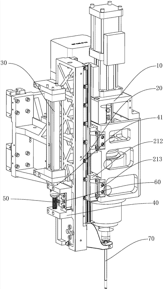
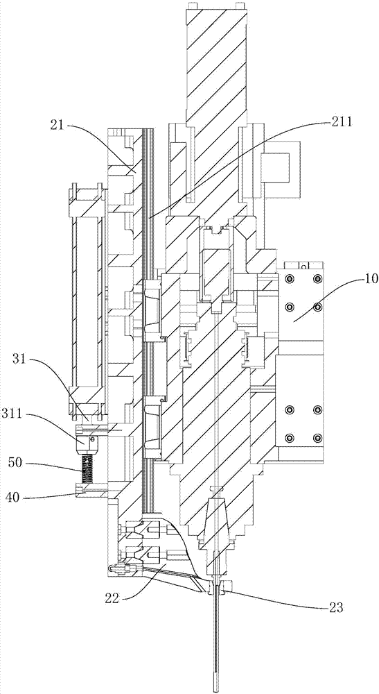
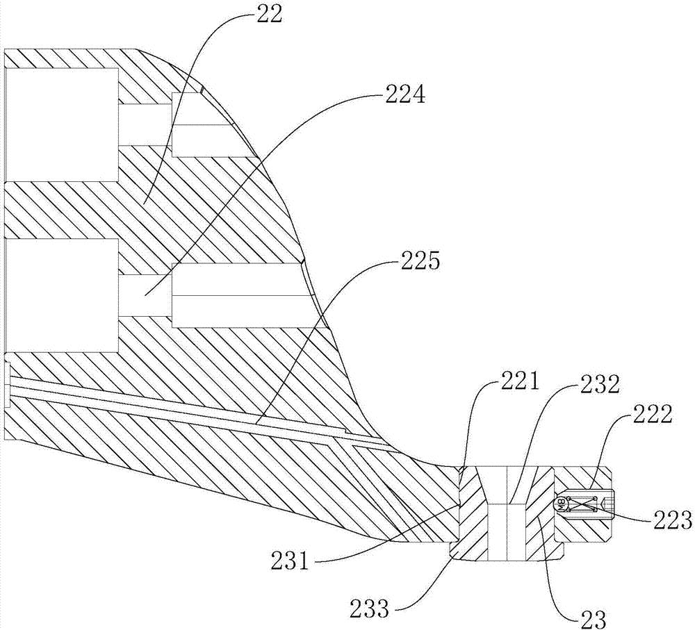
[0025] Such as Figure 1-3 As shown, the guiding mechanism of the embodiment of the present invention includes a main shaft frame 10, a guide sleeve assembly 20 slidably connected to the main shaft frame 10, and a driving device 30 for driving the guide sleeve assembly 20 to slide along the main frame 10, and the driving device 30 is fixedly connected On the spindle frame 10, the guide sleeve assembly 20 includes a sliding seat 21, a guide sleeve bracket 22 fixed to the bottom of the sliding seat 21, and a metal guide sleeve 23 fixed on the guide sleeve bracket 22. The sliding seat 21 is close to a part of the spindle frame 10. At least two guide rails 211 are provided on the side. Each guide r...


PUM


Abstract

The invention discloses a guide mechanism of a gun drill of a vertical numerical control drilling machine. The guide mechanism comprises a spindle frame, a guide sleeve assembly slidably connected with the spindle frame and a driving device used for driving the guide sleeve assembly to slide along the spindle frame. The driving device is fixedly connected to the spindle frame. The guide sleeve assembly comprises a sliding seat, a guide sleeve support fixedly connected to the bottom of the sliding seat and a metal guide sleeve fixed to the guide sleeve support. The side, close to the spindle frame, of the sliding seat is provided with at least two guide rails. At least two sliding blocks are arranged on each guide rail. The sliding blocks are fixedly connected with the spindle frame. The middle portion of the metal guide sleeve is provided with a through hole matched with the gun drill. The guide mechanism can conduct accurate guiding and positioning on the gun drill of the vertical numerical control drilling machine while the gun drill conducts deep hole drilling.

Description


Claims


Application Information

Patent Timeline
Owner 广东利工设备有限公司
Learn More