Piezoelectric drive type two-degree-of-freedom high-precision microoperation clamp

A piezoelectric drive and micro-operation technology, which is applied in metal processing, metal processing equipment, manufacturing tools, etc., can solve the problems that cannot meet the requirements of PMOF rotation at an angle, cannot guarantee the precise positioning of PMOF, and is not suitable for mass production. Achieve the effects of measurement and real-time feedback, compact structure, and low production cost

Inactive Publication Date: 2017-12-01
TIANJIN UNIV
View PDF7 Cites 15 Cited by
  • Summary
  • Abstract
  • Description
  • Claims
  • Application Information

AI Technical Summary

Problems solved by technology

So far, the assembly process of PMOF still mainly relies on manual delicate operation, the production cost is high and it is not suitable for mass production
[0003] The existing micro-manipulation grippers can be roughly divided into two types: single-degree-of-freedom and two-degree-of-freedom: for single-degree-of-freedom micro-manipulation grippers, only simple pick-and-place actions can be realized, which cannot meet the needs of rotating PMOF by an angle ; The existing two-degree-of-freedom micro-manipulation gripper usually has a complex structure and a large volume, and is still in the academic research stage. Even if the PMOF can be rotated, the precise positioning of the PMOF cannot be guaranteed

Method used


Image

  • Piezoelectric drive type two-degree-of-freedom high-precision microoperation clamp
  • Piezoelectric drive type two-degree-of-freedom high-precision microoperation clamp
  • Piezoelectric drive type two-degree-of-freedom high-precision microoperation clamp

Examples


Embodiment Construction

[0021] In order to further understand the invention content, characteristics and effects of the present invention, the following examples are given, and detailed descriptions are as follows in conjunction with the accompanying drawings:

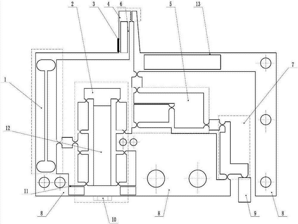
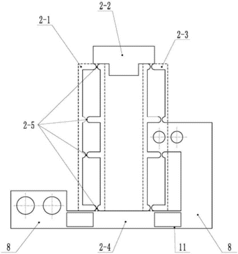
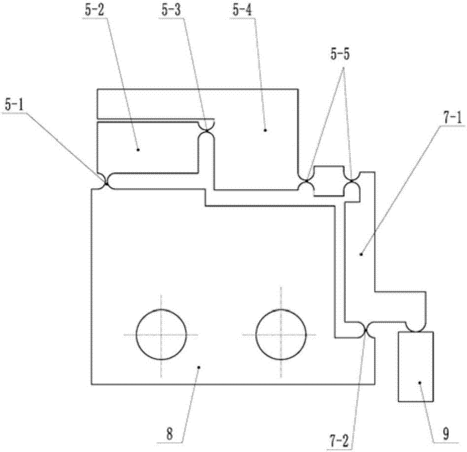
[0022] see Figure 1 ~ Figure 4 , the embodiment of the present invention protects a piezoelectric-driven two-degree-of-freedom high-precision micro-operation gripper, which is integrally formed by wire cutting of a plate, and includes a bridge-type displacement amplification mechanism 2 and an SR displacement amplification mechanism 5, The lever amplifying mechanism 7 and the base body 8, the bridge type displacement amplifying mechanism 2, the SR displacement amplifying mechanism 5, and the lever amplifying mechanism 7 are distributed on both sides of the center line, which is an asymmetric structure.

[0023] The bridge-type displacement amplifying mechanism 2 is distributed on the left side of the mechanism, and is provided with two movab...


PUM


Abstract

The invention discloses a piezoelectric drive type two-degree-of-freedom high-precision microoperation clamp. The piezoelectric drive type two-degree-of-freedom high-precision microoperation clamp comprises a bridge type displacement amplifying mechanism, a lever amplifying mechanism, an SR displacement amplifying mechanism and a base body. The bridge type displacement amplifying mechanism is provided with a movable upper cross beam and, a movable lower cross beam, a left four-connecting-rod mechanism and a right four-connecting-rod mechanism, wherein the upper cross beam and the lower cross beam are connected through the left four-connecting-rod mechanism and the right four-connecting-rod mechanism, the left four-connecting-rod mechanism and the right four-connecting-rod mechanism are each formed through connection by a flexible hinge I, and two flexible parallel double-plate mechanisms I which are connected with the base body are arranged at the two ends of the lower cross beam correspondingly; and a piezoelectric ceramic actuator I is arranged between the upper cross beam and the lower cross beam. A parallelogram mechanism formed through connection by a flexible hinge II is arranged on the left side of the bridge type displacement amplifying mechanism. A connecting beam perpendicular to the parallelogram mechanism is formed at the output end of the parallelogram mechanism, and a jaw is arranged on the connecting beam. The piezoelectric drive type two-degree-of-freedom high-precision microoperation clamp has the characteristics of being high in precision, high in response speed, low in manufacturing cost and the like.

Description

technical field [0001] The invention belongs to the field of micro-device packaging, in particular to a piezoelectric-driven two-degree-of-freedom high-precision micro-operation gripper. Background technique [0002] Polarization-maintaining fiber (PMOF) is a special fiber specially designed to transmit linearly polarized light. Unlike ordinary fibers, there is usually an angle error between the two optical fibers. To ensure the effectiveness of light transmission, the two PMOFs need to be rotationally aligned during assembly. So far, the assembly process of PMOF still mainly relies on manual delicate operation, the production cost is high and it is not suitable for mass production. [0003] The existing micro-manipulation grippers can be roughly divided into two types: single-degree-of-freedom and two-degree-of-freedom: for single-degree-of-freedom micro-manipulation grippers, only simple pick-and-place actions can be realized, which cannot meet the needs of rotating PMOF ...

Claims


Application Information

Patent Timeline
Patent Type & Authority Applications(China)
IPC IPC(8): B23P19/10
CPCB23P19/10
Inventor 时贝超王福军梁存满田延岭张大卫
Owner TIANJIN UNIV
Why Eureka
Try Eureka