A mechanical arm device on a precision mounting rail

A technology of robotic arms and mounting rails, used in mechanical conveyors, conveyors, conveyor objects, etc.

Active Publication Date: 2019-03-15
HARBIN INST OF TECH
View PDF5 Cites 0 Cited by
  • Summary
  • Abstract
  • Description
  • Claims
  • Application Information

AI Technical Summary

Problems solved by technology

Due to the particularity and complexity of the environment in the laboratory, there is no hoisting equipment and installation machinery that can meet the needs of this type of laboratory construction. How to realize the hoisting and precise installation of heavy experimental instruments in a small space has become a major issue at present. Key Issues in Special Laboratory Construction Planning

Method used


Image

  • A mechanical arm device on a precision mounting rail
  • A mechanical arm device on a precision mounting rail
  • A mechanical arm device on a precision mounting rail

Examples


Embodiment approach 1

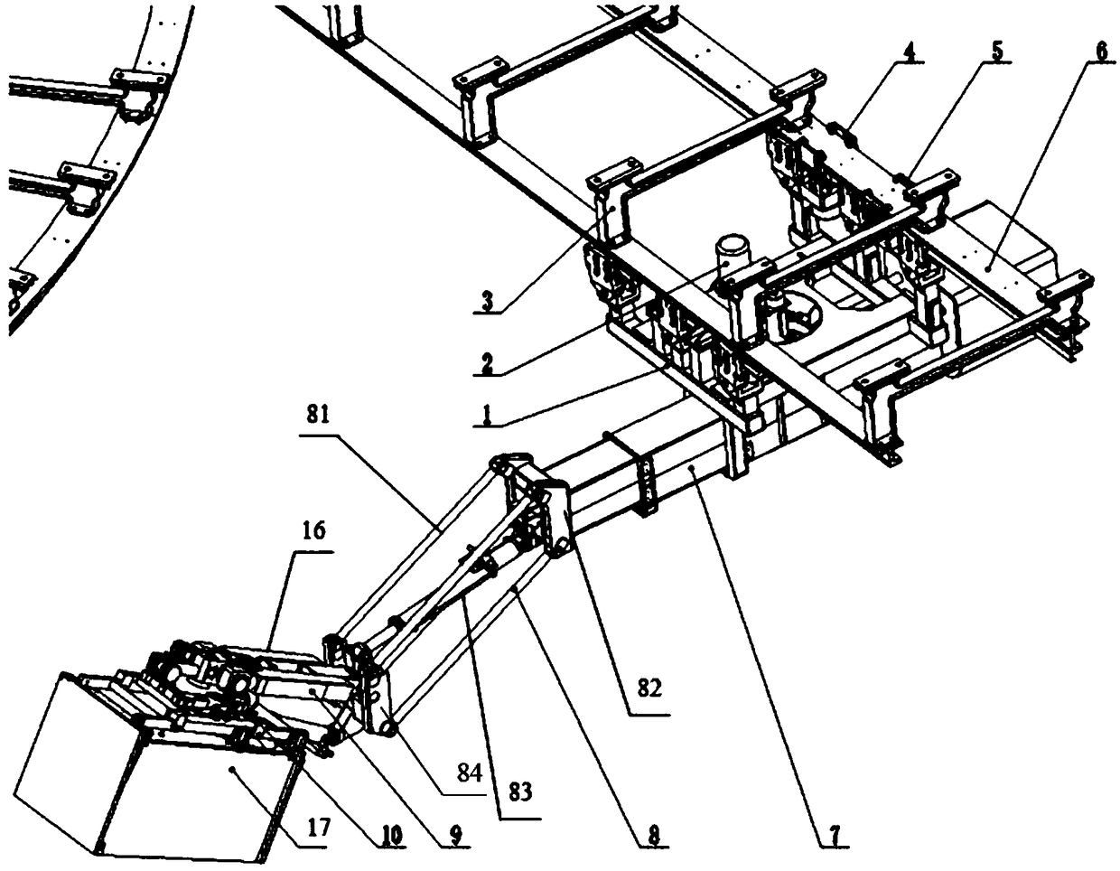
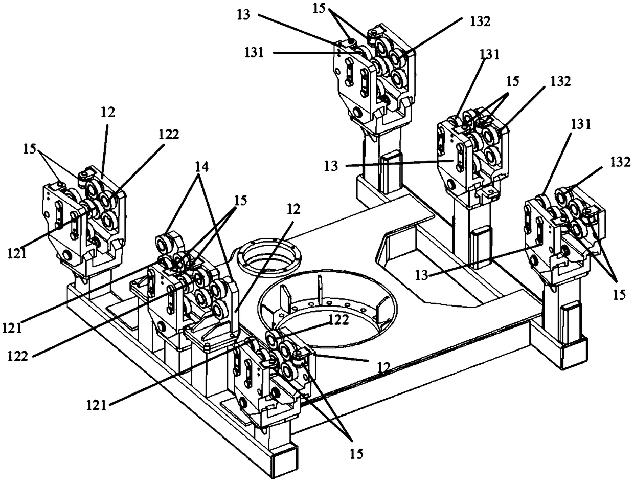
[0034] to combine Figure 1-8Describe this embodiment, a precision mounting rail mechanical arm device of this embodiment, the mechanical arm device includes a trailer 1, a slewing mechanism 2, a traction trolley 4, a track 6, a telescopic mechanism 7, a translation mechanism 8 and a manipulator 16; The trailer 1 is suspended on the track 6 by the trailer wheel set mechanism; the traction trolley 4 is suspended on the track 6 by the traction trolley wheel mechanism, and is fixedly connected with the trailer 1 for driving the trailer 1 to travel on the track 6; The bottom of the trailer 1 is fixed with a rotary mechanism 2; the bottom of the rotary mechanism 2 is fixed with a telescopic mechanism 7, which is used to drive the telescopic mechanism 7 to rotate 360° in the horizontal plane; the telescopic end of the telescopic mechanism 7 and the translation mechanism 8 connected to drive the translation mechanism 8 to reciprocate in the horizontal direction; the translation end o...

Embodiment approach 2

[0043] On the basis of Embodiment 1, this embodiment adds technical features: the mechanical arm device also includes a power-taking trolley 5; Suspended on the track 6, and the power-taking trolley 5 is fixedly connected with the trailer 1. The added technical features of this embodiment achieve the effect of providing power for the entire mechanical arm device.

[0044] Such as figure 1 As shown, in this embodiment, the power-taking trolley 5 is suspended on the track 6 through a set of wheels, the power-taking trolley 5 is connected with the trailer through a pin shaft, and the power-taking trolley 5 and the trailer 1 are driven on the track 6 by the traction trolley 4 together. Traveling; start the hydraulic system and the electric control system after the power-taking trolley 5 gets power, and provide power for the whole system.

Embodiment approach 3

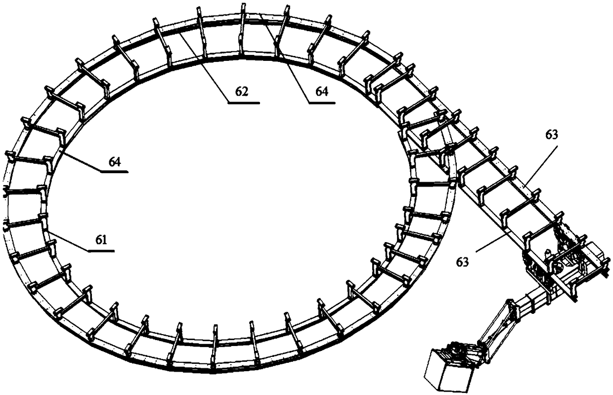
[0046] On the basis of the second embodiment, this embodiment adds technical features: the track 6 is also provided with a power transmission ring; the power transmission ring is electrically connected to the power-taking terminal of the power-taking trolley 5 to provide power for the mechanical arm device . The added technical features of this embodiment achieve the effect of providing power for the robotic arm device.

[0047] In this embodiment, the power transmission ring may be an aluminum power transmission ring.

[0048] In this embodiment, the electric power required by the electrical system of the manipulator is taken by the electric trolley 5, and two continuous aluminum power transmission rings can be arranged on the lower side of the upper wing plate of the outer rail 62 of the track 6, and the power transmission ring is at the end of the straight rail. The whole part is connected to the laboratory power supply, and the power-taking trolley 5 is equipped with a po...


PUM


Abstract

The invention relates to a precision installation on-track mechanical arm device and belongs to the technical field of precision instrument hoisting and precision installation in the mechanical engineering field. The mechanical arm device comprises a trailer, a rotation mechanism, a traction trolley, a track, a telescopic mechanism, a horizontal movement mechanism and a manipulator, wherein the trailer is suspended on the track through a trailer wheel set mechanism; the traction trolley is suspended on the track through a traction trolley wheel set mechanism and fixedly connected with the trailer; the rotation mechanism is fixed to the lower portion of the trailer; the telescopic mechanism is fixed below the rotation mechanism; the telescopic end of the telescopic mechanism is connected with the horizontal movement mechanism; and the horizontal movement end of the horizontal movement mechanism is connected with the manipulator. By adoption of the on-track running scheme, flexible obstacle avoidance in a narrow space is achieved through multi-degree-of-freedom coupled hoisting; and through combination of the primary in-place installation of a large-range movement mechanism with six-degree-of-freedom fine-adjustment precise docking, high-efficiency and high-precision docking installation of optical assemblies is achieved, and the precision installation on-track mechanical arm device is suitable for hoisting of heavy optical assemblies.

Description

technical field [0001] The invention relates to a mechanical arm device on a precision mounting rail, which belongs to the technical field of precision instrument hoisting and precision installation in the field of mechanical engineering, and is especially suitable for precision docking, hoisting and transportation of heavy optical instruments in a small space in a clean environment. Background technique [0002] With the development of major scientific experiment projects, many large-scale and highly integrated scientific laboratories have begun to be constructed and put into use. The arrangement of optical, mechanical and electrical equipment in a large laboratory is intricate, and the transportation channel and installation space are narrow. The docking installation, hoisting and transportation of various experimental equipment, especially optical instruments, require high stability and high precision. Due to the particularity and complexity of the environment in the labo...

Claims


Application Information

Patent Timeline
Patent Type & Authority Patents(China)
IPC IPC(8): B65G35/00B65G47/90
CPCB65G35/00B65G47/902
Inventor 王佳兰朋
Owner HARBIN INST OF TECH
Why Eureka
Try Eureka