Double-arm drying type hoisting permanent magnet

A driving type, permanent magnet technology, applied in the direction of load hanging components, transportation and packaging, etc., can solve the problem that the lifting permanent magnet cannot work normally, and achieve the effect of overcoming limitations and broadening the scope of application

Inactive Publication Date: 2017-12-01
CHANGCHUN UNIV
View PDF3 Cites 4 Cited by
  • Summary
  • Abstract
  • Description
  • Claims
  • Application Information

AI Technical Summary

Problems solved by technology

However, there are certain shortcomings and deficiencies in the transmission of the above-mentioned driving device and gears, which are specifically manifested in: it can only perform reliable operations on steel objects placed horizontally on the ground, and for objects placed on the ground with a large inclination angle Iron and steel suction objects sometimes cannot be picked up, and lifting permanent magnets do not work properly

Method used


Image

  • Double-arm drying type hoisting permanent magnet
  • Double-arm drying type hoisting permanent magnet
  • Double-arm drying type hoisting permanent magnet

Examples


Embodiment Construction

[0041] Specific embodiments of the present invention will be described in detail below in conjunction with the accompanying drawings.

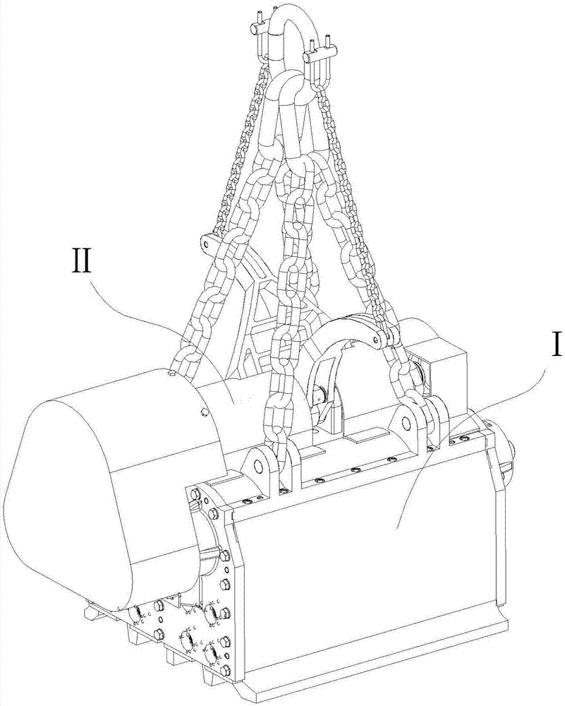
[0042] attached by figure 1 Shown: a double-arm driven lifting permanent magnet, including the magnetic system Ⅰ and the driving system Ⅱ arranged on the magnetic system Ⅰ, the magnetic system Ⅰ is located at the lower part of the driving system Ⅱ, and the driving system Ⅱ combines the rotation of the magnetic system Ⅰ The permanent magnet rotates to achieve the purpose of absorbing and removing heavy objects.

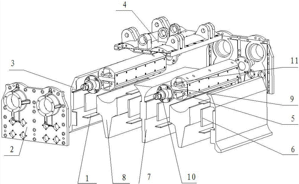
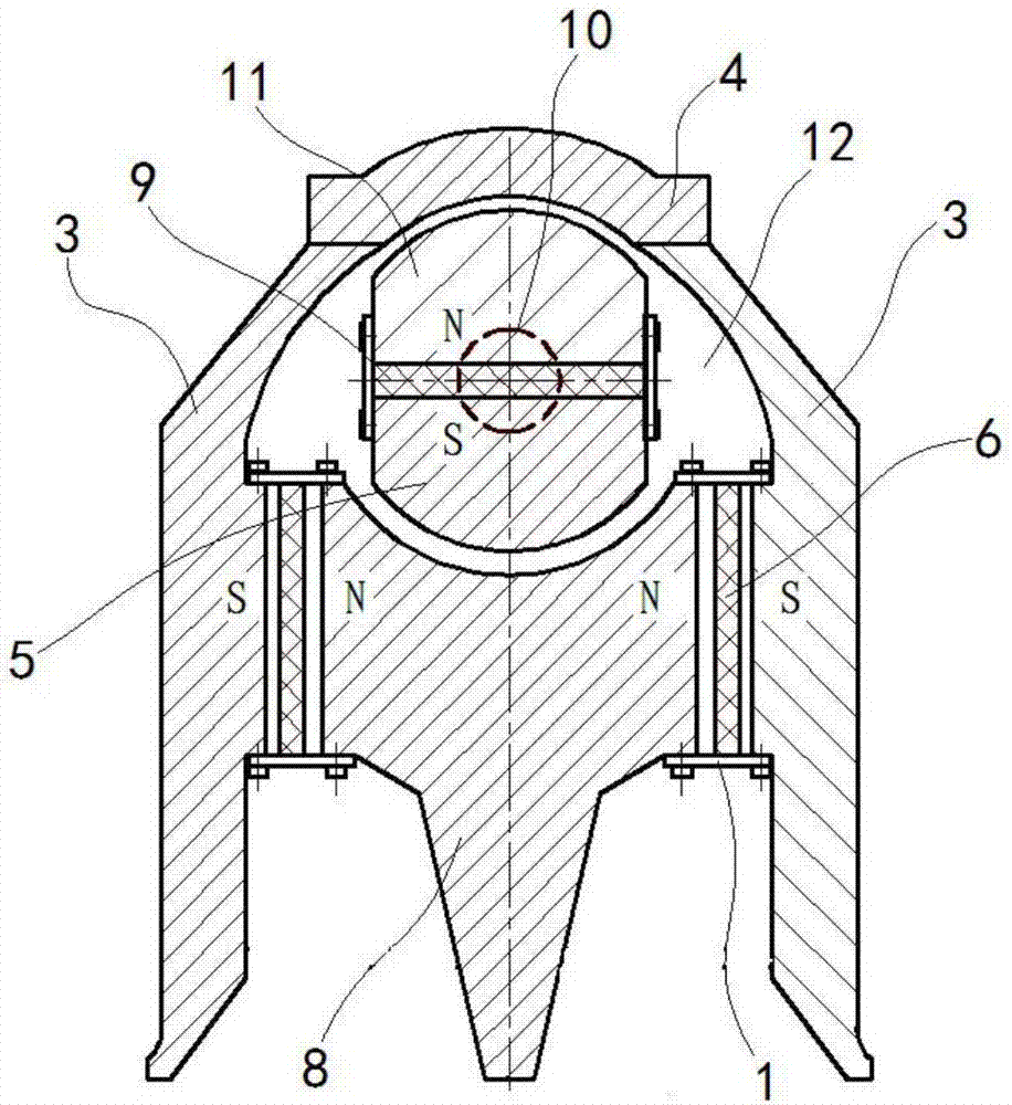
[0043] attached by figure 2 , 3 , 4 shows: the magnetic system I includes at least one magnetic system structure.

[0044] ①, by the attached image 3 Shown: When a single magnetic system structure is adopted, it includes a magnet fixing plate 1, an outer yoke 3, an upper cover 4, a lower magnetic pole piece 5, a lower magnet 6, a second inner yoke 8, an upper magnet 9, a rotating shaft 10, an upper Magnetic pole shoe 11; the sec...


PUM


Abstract

The invention relates to a double-arm drying type hoisting permanent magnet. The double-arm drying type hoisting permanent magnet comprises a magnetic system and a driving system, wherein the driving system is arranged on the magnetic system; the magnetic system is positioned at the lower part of the driving system; and the driving system achieves the goal of sucking heavy objects and unloading the heavy objects through the rotation of a rotary composite permanent magnet in the magnetic system. The double-arm drying type hoisting permanent magnet is characterized in that the driving system comprises driven cylindrical gears, a driving cylindrical gear, a hanging ring, a front small hanging chain, front hoisting chains, a back small hanging chain, back hoisting chains and a shaft system; the two driven cylindrical gears are respectively connected onto the end parts of a rotating shaft, and are engaged with the driving cylindrical gear arranged in the middle; the driving cylindrical gear is connected with the end part of the shaft system; one ends of the two front hoisting chains and the two back hoisting chains are respectively connected with an upper cover through a hanging lug arranged on the upper cover, and the other ends are connected onto the hanging ring; one end of the front small hanging chain is connected with the end part of a front swinging rod arranged on the shaft system; one end of the back small hanging chain is connected with the end part of a back swinging rod arranged on the shaft system; and the other ends of the front and back small hanging chains are connected onto the hanging ring. The permanent magnet has the advantages that the structure is simple and reasonable; and the application range of the hoisting permanent magnet is expanded.

Description

technical field [0001] The invention belongs to the technical field of lifting equipment, in particular to a double-arm driven lifting permanent magnet. Background technique [0002] In the prior art (ZL02126633.6, ZL92245257.1 and ZL92240596.4) discloses a lifting permanent magnet for lifting scrap iron and steel, its structure is described like this: one end of the small lifting chain is connected to the lifting ring of the large lifting chain of the lifting permanent magnet The other end of the small hanging chain is connected to the tail end of the swing rod equipped with pawls. The other end of the swing rod is bifurcated, and the empty sleeve is on both sides of the ratchet wheel in the middle of the drive shaft. A gear is also installed on one end of the drive shaft. Through this system (called the driving device), when the crane lifts the permanent magnet, as the lifting ring rises, the small lifting chain is gradually straightened, and then drives the pendulum to ro...

Claims


Application Information

Patent Timeline
Patent Type & Authority Applications(China)
IPC IPC(8): B66C1/04B66C1/12
CPCB66C1/04B66C1/125
Inventor 丁宁
Owner CHANGCHUN UNIV
Why Eureka
Try Eureka