Compact spinning tension bracket overturning tool

A technology of frame turning and compact spinning, applied in spinning machine, textile and papermaking, drafting equipment, etc., to achieve the effect of easy turning

Inactive Publication Date: 2020-10-16
江阴市华方新技术科研有限公司
View PDF0 Cites 0 Cited by
  • Summary
  • Abstract
  • Description
  • Claims
  • Application Information

AI Technical Summary

Problems solved by technology

[0004] The technical problem to be solved by the present invention is to provide an overturning tool for the compact spinning tension frame in view of the above-mentioned prior art, which can solve the problem of the existing compact spinning tension frame under the premise that the structure of the existing compact spinning tension frame remains unchanged and can be used normally. Overturning problem, it is easy, convenient and reliable to realize the overturning of the compact spinning tension frame, and the tension frame will not be deformed when it is turned over, and will not cause pollution, deformation and other effects on other parts

Method used


Image

  • Compact spinning tension bracket overturning tool
  • Compact spinning tension bracket overturning tool
  • Compact spinning tension bracket overturning tool

Examples


Embodiment 1

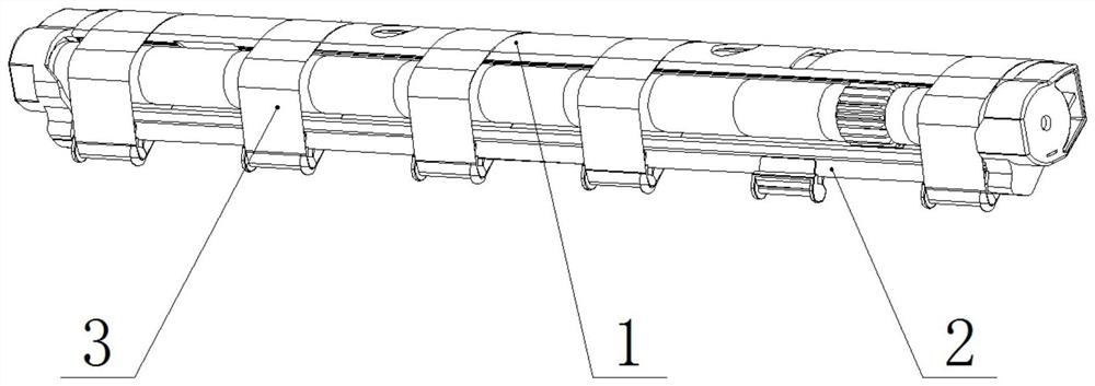
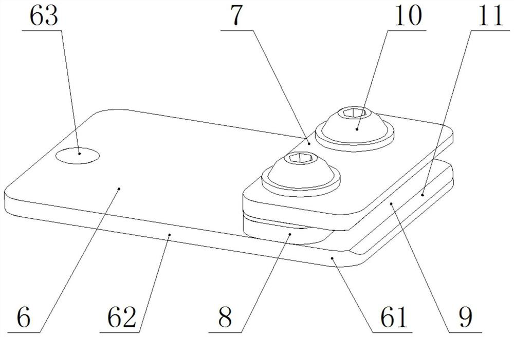
[0045] see Figure 3 ~ Figure 7 , a kind of compact spinning tension rack turnover tool that the present invention relates to, it comprises base plate 6, and described base plate 6 comprises front clamping part 61 and rear pinching part 62, and the position of described front clamping part 61 is provided with clamping plate 7. A backing plate 8 is provided between the front clamping portion 61 and the clamping plate 7, and the clamping plate 7 and the front clamping portion 61 form a clamping bayonet 9 at the front side of the backing plate 8;

[0046] The base plate 6, the clamping plate 7 and the backing plate 8 are connected by fasteners 10;

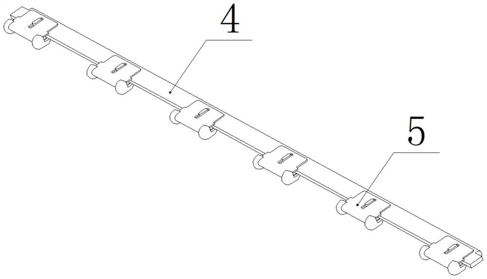
[0047] The height of the clamping bayonet 9 is greater than the thickness of the tension frame rod 4;

[0048] The front holding part 61 and the rear holding part 62 are integrally structured;

[0049] Both the front clamping part 61 and the rear clamping part 62 are planar plate structures;

[0050] The length of the rear gripping...

Embodiment 2

[0060] Such as Figure 8 As shown, the difference between this embodiment and Embodiment 1 is that: the base plate 6 , the clamping plate 7 and the backing plate 8 are connected by welding or bonding.

Embodiment 3

[0062] Such as Figure 9 , Figure 10 As shown, the difference between this embodiment and Embodiment 1 is that the substrate 6 includes a front clamping portion 61 and a rear clamping portion 62, and there are multiple front clamping portions 61, and the multiple front clamping portions 61 are left and right Arranged side by side, a relief slot 64 is formed between two adjacent front clamping portions 61 .


PUM


Abstract

The invention relates to a compact spinning tension bracket overturning tool. The tool comprises a base plate (6), the base plate (6) comprises a front clamping part (61) and a rear pinching part (62), a clamping plate (7) is arranged at the position of the front clamping part (61), a base plate (8) is arranged between the front clamping part (61) and the clamping plate (7), and the clamping plate(7) and the front clamping part (61) form a bayonet (9) in front of the base plate (8). According to the compact spinning tension bracket turnover tool, on the premise that the structure of an existing compact spinning tension bracket is not changed and normal use is guaranteed, the overturn problem of the existing compact spinning tension bracket can be solved, the overturn of the compact spinning tension bracket is easy, convenient and reliable, the tension bracket does not deform in the overturn process, and other parts are not polluted or deformed.

Description

technical field [0001] The invention relates to an overturning tool for a compact spinning tension frame, which belongs to the technical field of textile machinery. Background technique [0002] With the progress and development of spinning technology, compact spinning technology and compact spinning devices have been widely used in the market, especially the negative pressure four-roller compact spinning device. This device has a common feature: corresponding to compact spinning The special-shaped tube assembly includes parts such as a grid ring and a tension frame. The grid ring needs to be supported by the tension frame and generate tension on the grid ring. Among them, the compact spinning tension frame of Toyota Corporation of Japan has less flower accumulation, stable operation, and stable yarn index, so the compact spinning special-shaped tube components using the compact spinning tension frame similar to Toyota's structure have a very high market share. [0003] The...

Claims


Application Information

Patent Timeline
Patent Type & Authority Applications(China)
IPC IPC(8): D01H5/72D01H13/10
CPCD01H5/72D01H13/10
Inventor 闫中旭汪仁晓陆荣海严朴顾垚
Owner 江阴市华方新技术科研有限公司
Why Eureka
Try Eureka