Double-circuit drive rotary lifting permanent magnet

A two-way drive, permanent magnet technology, applied in the direction of load hanging components, transportation and packaging, to achieve the effect of widening the scope of application, overcoming limitations, and stable and reliable turning

Inactive Publication Date: 2016-07-27
CHANGCHUN UNIV
View PDF8 Cites 0 Cited by
  • Summary
  • Abstract
  • Description
  • Claims
  • Application Information

AI Technical Summary

Problems solved by technology

But at this time, the working magnetic pole surface of the lifting permanent magnet has left the surface of the steel to be sucked, so that the lifting permanent magnet in the suction state cannot absorb the steel to be sucked

Method used


Image

  • Double-circuit drive rotary lifting permanent magnet
  • Double-circuit drive rotary lifting permanent magnet
  • Double-circuit drive rotary lifting permanent magnet

Examples


Embodiment Construction

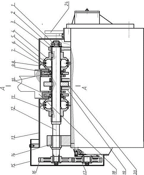
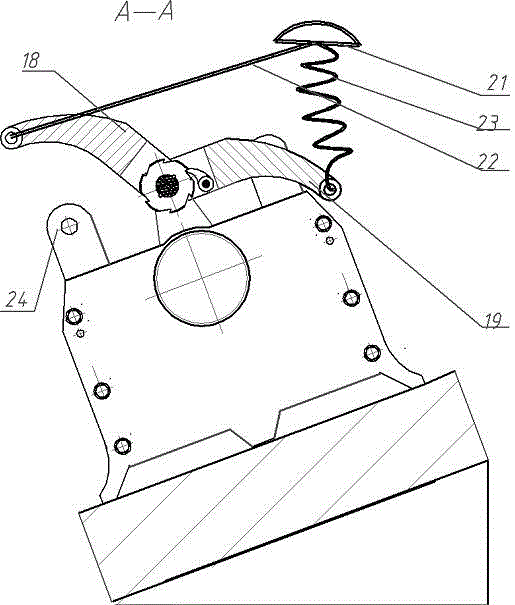
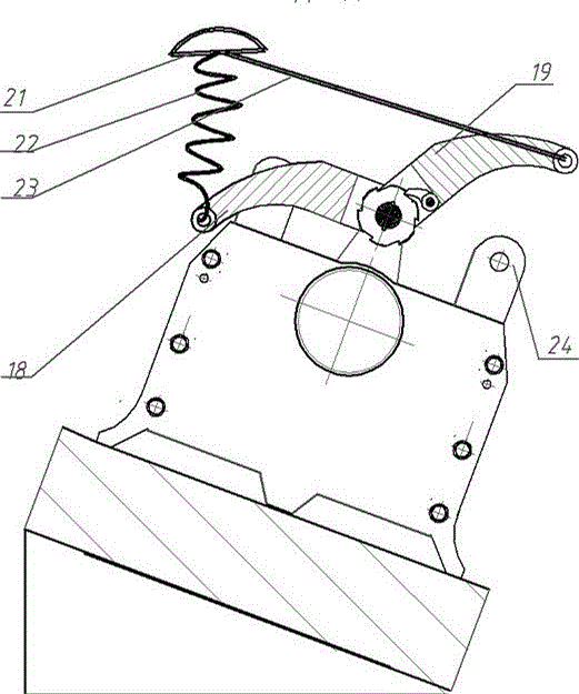
[0010] In order to make the two sets of drive mechanisms rotate the drive shaft in the same direction, the swing rod 19 in the front side ratchet swing rod drive mechanism is vacantly sleeved on the drive shaft 12, and the ratchet 20 is connected with the drive shaft 12 by a key. The ratchet 10 and the fork 18 of the rear side ratchet fork drive mechanism are all sleeved on the drive shaft 12 by sliding bearings, and can be relatively rotated with the drive shaft. The fork 18 and the fork 19 rotate in opposite directions during the process of lifting the object to be sucked. The ratchet 10 is fixed together with the conical disc gear 7, the conical disc gear 7 meshes with the bevel gear 5 supported by the positioning frame 6, the bevel gear 5 meshes with the conical hub gear 4, and the conical hub gear 4 is connected to the drive shaft through the key 11 12 connections. In this way, the rear ratchet swing bar drive mechanism and the front ratchet swing bar drive mechanism can...


PUM


Abstract

The invention discloses a double-circuit drive rotary lifting permanent magnet. A double-circuit driving device consisting of a small lifting chain, a swing rod, a ratchet wheel, a bevel shaft sleeve gear and the like is used for simply and conveniently converting upward traction of a crane to torque applied to a driving shaft to rotate in the same direction; and a rotating magnetic system for driving a magnetic circuit rotates by 180 degrees to realize suction and unloading of absorbed steel and iron objects with large inclined angle with the ground. The double-circuit drive rotary lifting permanent magnet can quickly operate like a lifting electromagnet, and can absorb the absorbed steel and iron objects with a weight of dozens of tonnages. The double-circuit drive rotary lifting permanent magnet is a great breakthrough of a driving part technology of the lifting permanent magnet, and widens the application range of the lifting permanent magnet.

Description

technical field [0001] The invention belongs to the technical field of lifting equipment. Background technique [0002] In the invention patents (ZL02126633.6, ZL92245257.1 and ZL92240596.4) that we applied for earlier, one end of the small hanging chain is connected to the lifting ring of the large lifting chain of the lifting permanent magnet, and the other end of the small hanging chain is connected to the ring equipped with a pawl. The tail end of the swing rod, the other end of the swing rod is bifurcated, and the empty sleeve is on both sides of the ratchet in the middle part of the drive shaft, and a gear is also housed on one end of the drive shaft. Through this system (called the driving device), when the crane lifts the permanent magnet, as the lifting ring rises, the small lifting chain is gradually straightened, and then drives the pendulum to rotate. At the same time, the ratchet on it makes the ratchet rotate a certain angle. Because the gear on one end of th...

Claims


Application Information

Patent Timeline
Patent Type & Authority Applications(China)
IPC IPC(8): B66C1/04
CPCB66C1/04B66C1/125
Inventor 丁宁马世强赵昌龙张丁佟
Owner CHANGCHUN UNIV
Why Eureka
Try Eureka