Bridge expansion joint device

A technology of expansion joints and bridges, applied in the direction of bridges, bridge parts, bridge construction, etc., can solve the problems affecting the driving speed, comfort and safety, uneven bearing capacity of the tooth plate, and poor bearing capacity of the device, so as to improve the practicability. and applicability, bearing capacity enhancement, noise reduction effect

Inactive Publication Date: 2017-12-01
MIANYANG JIUDING ZHIYUAN INTPROP OPERATION CO LTD
View PDF0 Cites 13 Cited by
  • Summary
  • Abstract
  • Description
  • Claims
  • Application Information

AI Technical Summary

Problems solved by technology

Where expansion joints are set, railings and bridge deck pavement must be disconnected. The function of bridge expansion joints is to adjust the displacement and connection between the superstructure caused by vehicle loads and bridge building materials. Once the expansion device of the skew bridge If it is damaged, it will seriously affect the speed, comfort an...

Method used


Image

  • Bridge expansion joint device
  • Bridge expansion joint device
  • Bridge expansion joint device

Examples


Embodiment 1

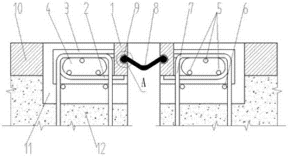
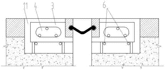
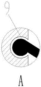
[0048] As shown in the accompanying drawings, a bridge expansion joint device includes a special-shaped steel plate 1, an anchor bar 2 and a waterproof adhesive tape 8; The two ends of the special-shaped steel plate 1 are respectively connected to two groups of special-shaped steel plates 1; a number of anchor bars 2 are evenly arranged on the special-shaped steel plate 1; anchor plates-3 are interlaced with the anchor bars 2 on the special-shaped steel plate 1; Steel plate 1 connection.

[0049] When the anchor bar 2 is connected with the anchor plate-3 and is connected with the opposite-shaped steel bar; the integrally connected anchor bar 2 and the anchor plate-3 are provided with several groups, and each group is evenly arranged on the special-shaped steel bar at a certain distance, and is perpendicular to the special-shaped steel bar Connection, the anchor bars 2 connected to the two sets of special-shaped steel bars and the anchor plate 1 3 are arranged oppositely or alt...

Embodiment 2

[0054] A kind of installation method of the bridge expansion joint device based on embodiment 1, comprises the following steps:

[0055] 1) Determine the installation width value of the bridge expansion joint according to the actual temperature;

[0056] 2) Clean the slot to make it reach the designed width and depth, so that the slot width of the reserved slot is greater than the installation width of the bridge expansion joint;

[0057] 3) Hoist the bridge expansion device into the reserved slot so that the top surface of the special-shaped steel plate is at the same elevation as the bridge deck, and adjust the position of the bridge expansion device so that the distance between the center line and the reserved two sets of special-shaped steel plates The centerline of the gap is aligned and its length is aligned with the width of the bridge;

[0058] 4) At the joint of the anchor plate on the special-shaped steel plate, the steel bar with a diameter of Ф18 or more is used f...


PUM


Abstract

The invention discloses a bridge expansion joint device, which comprises a special-shaped steel plate, an anchor bar and a waterproof tape; the special-shaped steel plate is provided with two groups, and the two groups of special-shaped steel plates are arranged to form a certain gap; the two ends of the waterproof tape are respectively connected to the Two sets of special-shaped steel plates; several anchor bars are evenly arranged on the special-shaped steel plates; on the special-shaped steel plates, an anchor plate one is also interlaced with the anchor bars; the anchor plate one is connected with the special-shaped steel plates; The special-shaped anchor bar and the corresponding anchor plate are arranged on the steel plate of the heterosexual expansion joint, so that the bridge expansion joint device of the present invention has a strong bearing capacity and is not easily deformed. Its structural size and installation position are reasonable, the noise is low, its bearing capacity is greatly improved, and its service life Long, with good usability.

Description

technical field [0001] The invention relates to an expansion joint device, in particular to a bridge expansion joint device. Background technique [0002] Bridge expansion joints refer to expansion joints usually set between two girder ends, between girder ends and abutments, or at the hinged position of the bridge in order to meet the deformation requirements of the bridge deck. It is required that the expansion joints can freely expand and contract in two directions parallel to and perpendicular to the bridge axis, and are firm and reliable. The vehicles should run smoothly without sudden jumps and noises; they should be able to prevent rainwater and garbage from infiltrating and blocking; installation, inspection, and maintenance , Elimination of dirt should be simple and convenient. [0003] At present, bridge expansion joints generally have butt joint type, steel support type, combined shear type, modulus support type and elastic device. The butt joint expansion joint...

Claims


Application Information

Patent Timeline
IPC IPC(8): E01D19/06
CPCE01D19/067
Inventor 宋岑涔
Owner MIANYANG JIUDING ZHIYUAN INTPROP OPERATION CO LTD
Why Eureka
Try Eureka