High-energy-efficiency air source heat pump

An air source heat pump, high energy efficiency technology, applied in the field of heat pump, can solve problems such as bonding, evaporator not working normally, affecting refrigerant transmission, etc., to achieve the effect of improving safety, improving strength and deformation resistance, and high energy efficiency

Inactive Publication Date: 2017-12-01
舟山达康科技有限公司
View PDF9 Cites 0 Cited by
  • Summary
  • Abstract
  • Description
  • Claims
  • Application Information

AI Technical Summary

Problems solved by technology

By setting the sleeve-type evaporator, both the first refrigerant pipe and the second refrigerant pipe in the sleeve-type evaporator can transmit refrigerant, so that the sleeve-type evaporator can make full use of the waste heat of the refrigerant flowing back to the air source heat pump, The air source heat pump still has a high energy efficiency ratio in a low temperature environment, and the heating efficiency of the air source heat pump is improved. However, the air source heat pump of the invention may have the first refrigerant pipe and the second refrigerant pipe bonded together, which affects the refrigerant transmission. , may cause the evaporator to not work properly

Method used


Image

  • High-energy-efficiency air source heat pump
  • High-energy-efficiency air source heat pump
  • High-energy-efficiency air source heat pump

Examples


Embodiment 1

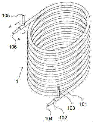
[0022] Such as Figure 1~5 As shown, the high-energy-efficiency air source heat pump includes a casing 4, an evaporator 1 and a compressor 3 arranged at the inner bottom of the casing 4, the compressor 3 is provided with a compressor inlet 301 and a compressor outlet 302, and the side wall of the casing 4 The lower end is provided with a total refrigerant inlet 5 and a total refrigerant outlet 6, the total refrigerant pipe inlet 5 is connected to the evaporator 1, the evaporator 1 is connected to the compressor 3, the compressor 3 is connected to the total refrigerant pipe outlet 6, the evaporator 1 and the compressor 3 is provided with a heat insulation board 7, the edge of the heat insulation board 7 is connected with the inner wall of the shell 4, and a heat insulation board 7 is provided between the evaporator 1 and the compressor 3, which can effectively prevent the heat emitted by the evaporator 1 from affecting the compressor. 3, to improve the service life of the compr...

Embodiment 2

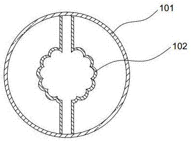
[0032] Such as Figure 1~5 As shown, in an air source heat pump with high energy efficiency, in actual operation, the total refrigerant inlet 5 is connected to the first refrigerant pipe inlet 105, the first refrigerant pipe outlet 103 is connected to the second refrigerant pipe inlet 104, and the second refrigerant pipe outlet 106 and The compressor inlet 301 is connected, the compressor outlet 302 is connected with the main refrigerant pipe outlet 6, the refrigerant enters from the main refrigerant inlet 5, and when working, the compressor 3 is turned on to make it work, and the refrigerant flows into the evaporator 1 from the main refrigerant pipe inlet 5 The first refrigerant pipe inlet 105 of the first refrigerant pipe flows into the second refrigerant pipe inlet 104 from the first refrigerant pipe outlet 103, and flows into the compressor inlet 301 from the second refrigerant pipe outlet 106. The compressor 3 converts the refrigerant from low temperature and low pressure ...


PUM


Abstract

The invention provides a high-energy-efficiency air source heat pump, and belongs to the heat pump technology. The high-energy-efficiency air source heat pump comprises a shell, an evaporator and a compressor, wherein the evaporator and the compressor are arranged at the bottom in the shell. A main refrigerant inlet and a main refrigerant outlet are formed in the lower end of one side wall of the shell. The main refrigerant pipe inlet is connected with the evaporator. The evaporator is connected with the compressor. The compressor is connected with the main refrigerant pipe outlet. A heat insulation plate is arranged between the evaporator and the compressor. The edge of the heat insulation plate is connected with the inner wall of the shell. The air source heat pump is reliable in structure connection and high in work energy efficiency; the evaporator can effectively utilize waste heat of a refrigerant, and the refrigerant entering the compressor can have high temperature; and the air source heat pump still has the high energy efficiency ratio under the low temperature condition, and the heating efficiency of the air source heat pump is improved.

Description

technical field [0001] The invention belongs to heat pump technology, in particular to an air source heat pump with high energy efficiency. Background technique [0002] Air energy (source) heat pump is a kind of heat pump technology, which has the reputation of "porter of natural energy". The equipment for producing cold (hot) air or cold (hot) water from a heat source. The main components include heat exchange equipment on the heat side, heat exchange equipment on the heat source side, and compressors. The air energy (source) heat pump uses the heat in the air as a low-temperature heat source, conducts heat exchange through the condenser or evaporator in the traditional air conditioner, and then extracts or releases heat energy through the circulation system, and uses the unit circulation system to transfer the energy to the building Inside, to meet the needs of users for domestic hot water, floor heating or air conditioning. [0003] For example, in the prior art, the C...

Claims


Application Information

Patent Timeline
Patent Type & Authority Applications(China)
IPC IPC(8): F25B1/00F25B39/02F28F19/02C09D127/06C09D161/14C09D161/20C09D5/08C09D7/12
CPCC08K2003/0812C08L2205/035C09D5/08C09D127/06F25B1/005F25B39/02F28F19/02C08L61/14C08L61/20C08K3/08Y02P20/10
Inventor 谢超
Owner 舟山达康科技有限公司
Why Eureka
Try Eureka