Reference signal and multiple access resource mapping method and equipment

A technology of reference signal and mapping method, applied in the directions of pilot signal allocation, multiple use of transmission path, sub-channel allocation of transmission path, etc., can solve the problem of reducing system throughput, large signaling overhead, increasing data transmission delay, etc. question

Active Publication Date: 2017-12-01
BEIJING SAMSUNG TELECOM R&D CENT +1
View PDF10 Cites 27 Cited by
  • Summary
  • Abstract
  • Description
  • Claims
  • Application Information

AI Technical Summary

Problems solved by technology

It can be seen that when there are a large number of connected terminals in the system, a large amount of additional signaling overhead is required, which also increases the delay of data transmission and reduces the throughput of the system.

Method used


Image

  • Reference signal and multiple access resource mapping method and equipment
  • Reference signal and multiple access resource mapping method and equipment
  • Reference signal and multiple access resource mapping method and equipment

Examples


Embodiment 1

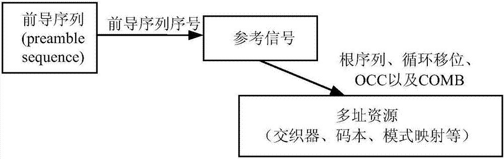
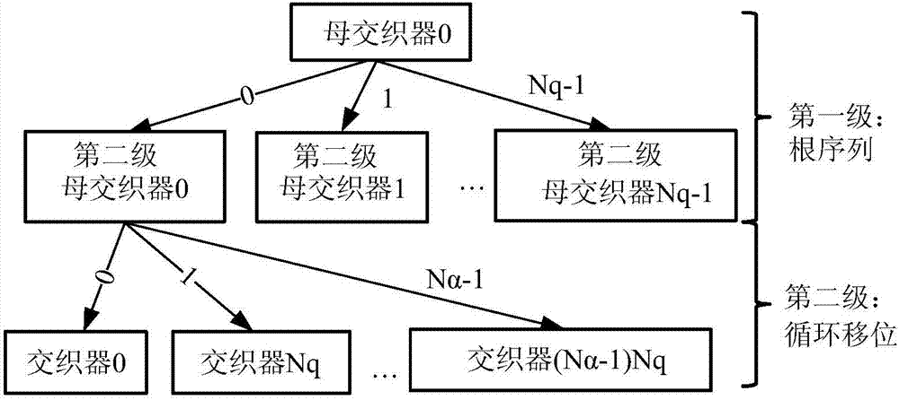
[0070] This embodiment introduces a one-to-one mapping method between a reference signal and an interleaver for IDMA. In an actual system, the reference signal usually consists of four parameters, namely root sequence, cyclic shift, OCC and COMB. Here, a method of mapping out an interleaver from two parameters of a reference signal is considered. The two parameters may be any two of the four reference signal composition parameters, and this embodiment describes the case where the two parameters are root sequence and cyclic shift. Specifically, the reference signal sequence is generated as follows:

[0071]

[0072] where u and v are used to determine the root sequence , α is the cyclic shift, n=0, 1, . . . , T-1 is the nth sample point of the reference signal, and T is the length of the reference signal. When the two terminals come from different cells, or the resource blocks (Resource Block, RB) lengths occupied by their transmission data are different, the reference...

Embodiment 2

[0100] Embodiment 1 introduces a mapping process for a system using an interleaver as a multiple access resource. In this embodiment, a system using power as a multiple access resource is considered, such as NOMA in the uplink power domain. In this type of system, by performing power control, the receiving power of signals sent by different terminals is different, so as to achieve the purpose of distinguishing users. At this time, power control can be completed by establishing a mapping relationship with the reference signal.

[0101] This embodiment considers a method of mapping multiple access power from two parameters of a reference signal, ie root sequence and cyclic shift. First, use the pre-agreed power reference in the system to generate a second-level power reference according to certain rules according to the first parameter of the reference signal; then, using the generated second-level power reference, according to the second parameter of the reference signal, Pow...

Embodiment 3

[0107] Embodiment 1 and Embodiment 2 respectively introduce a mapping process for a system using an interleaver and received power as multiple access resources. In this embodiment, consider systems that use codebooks and / or pattern maps as multiple access resources, such as SCMA, MUSA, PDMA, NCMA, NOCA, and RSMA. In such systems, resource pools (codebook design and pattern mapping pattern) rely on relatively complex optimization algorithms, so it is difficult to generate them in a simple way based on a parent resource. In addition, it should be noted that the mapping method of this embodiment is also applicable to multiple access systems using the interleaver and / or power as the multiple access system. Circumstances arising from the methods mentioned in the second paragraph. That is to say, this embodiment is applicable to the case where the multiple access resource is any of the following: space resource, bit-level interleaver, symbol-level interleaver, power, non-orthogonal...


PUM


Abstract

The invention discloses a reference signal and multiple access resource mapping method comprising the steps that a reference signal used for uplink data transmission is determined; multiple access resources are determined according to the mapping relation between the reference signal and the multiple access resources; and communication is performed by using the multiple access resources. The mapping method can also be applied to a scheduling-free system. The root sequence index, the cyclic shift, the OCC index and the COMB index of the reference signal used for uplink data transmission can be mapped out by the leader sequence through the set rules according to the selected leader sequence, and then the multiple access resources can be mapped out according to the mapping method. The invention also discloses reference signal and multiple access resource mapping equipment. The signaling overhead can be reduced by applying the technical scheme.

Description

technical field [0001] The present application relates to the technical field of wireless communication, and in particular to a method and device for mapping reference signals and multiple access resources of a multiple access system. Background technique [0002] With the rapid development of the information industry, especially the growing demand from the mobile Internet and the Internet of Things (IoT, internet of things), it brings unprecedented challenges to future mobile communication technologies. For example, according to the report ITU-R M.[IMT.BEYOND 2020.TRAFFIC] of the International Telecommunication Union ITU, it can be predicted that by 2020, the growth of mobile traffic will increase by nearly 1,000 times compared to 2010 (4G era), and the number of user equipment connections will also increase. It will exceed 17 billion. As massive IoT devices gradually penetrate into mobile communication networks, the number of connected devices will become even more astonis...

Claims


Application Information

Patent Timeline
Patent Type & Authority Applications(China)
IPC IPC(8): H04L5/00
CPCH04L5/0048H04L1/0071
Inventor 郝辰曦钱辰喻斌付景兴熊琦
Owner BEIJING SAMSUNG TELECOM R&D CENT
Why Eureka
Try Eureka