Head-up display device

A head-up display device and display mode technology, applied in measuring devices, optical observation devices, transportation and packaging, etc., can solve the problem that drivers cannot grasp information intuitively

Inactive Publication Date: 2017-12-01
MAZDA MOTOR CORP
View PDF11 Cites 6 Cited by
  • Summary
  • Abstract
  • Description
  • Claims
  • Application Information

AI Technical Summary

Problems solved by technology

Therefore, under the technique of Patent Document 1, if the information is displayed, the driver sometimes cannot intuitively grasp the required information

Method used


Image

  • Head-up display device
  • Head-up display device
  • Head-up display device

Examples


no. 1 approach

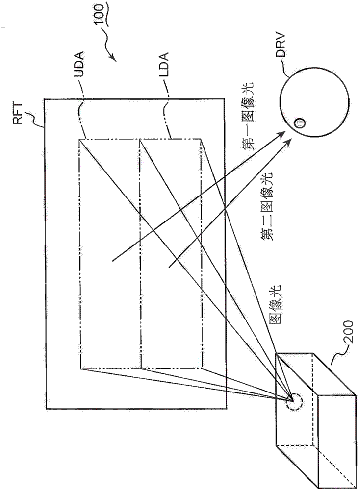
[0037] The inventors of the present invention have found that if information is displayed along the driver's driving behavior pattern, the driver can intuitively acquire the information. When a driver looks at factors outside the vehicle (for example, a sign indicating a legal speed, a line drawn on the road surface to indicate a driving lane, and a preceding vehicle), the driver's eyes are often directed upward. On the other hand, since most of the information on the vehicle itself is displayed on the indicator panel, the driver often looks down in order to obtain the information on the vehicle itself. In the first embodiment, a head-up display device that displays information along such a driving action pattern will be described.

[0038] figure 1 It is a conceptual diagram of the head-up display device 100 of the first embodiment. refer to figure 1 The head-up display device 100 will be described.

[0039] The head-up display device 100 includes a projection device 200 ...

no. 3 approach

[0057] The head-up display device can display various images based on the principle described in connection with the first embodiment and the second embodiment. In the third embodiment, an exemplary image displayed on a head-up display device will be described.

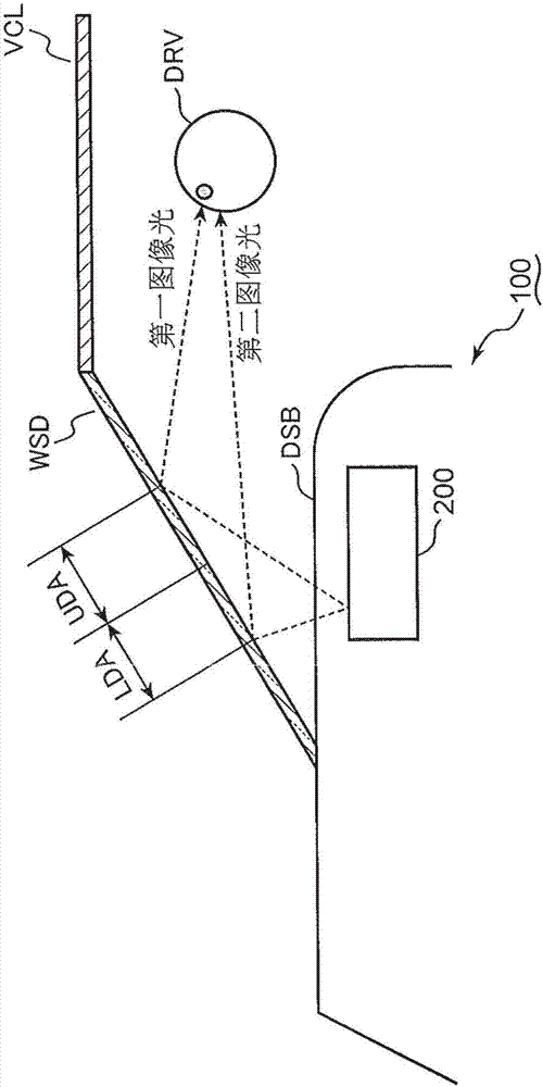
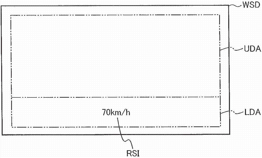
[0058] Figure 3A to Figure 3D Respectively through the head-up display device 100 (refer to figure 2 ) is a schematic image represented by image light emitted toward the windshield WSD. The symbols used in common between the first embodiment to the third embodiment mean that the elements attached with the common symbols have the same functions as those in the first embodiment and / or the second embodiment. Therefore, the description of the first embodiment and / or the second embodiment refers to these elements. refer to Figure 2 to Figure 3D An exemplary image displayed by the head-up display device 100 will be described.

[0059] Figure 3A to Figure 3D A windshield WSD is schematically shown, respectively. A...

no. 4 approach

[0067] As described in connection with the first to third embodiments, if information on external factors outside the vehicle is included, the head-up display device emits image light to an upper region. On the other hand, the head-up display device emits image light to a lower area in order to display the information of the vehicle itself. The head-up display device may emit, as image light, boundary light indicating a boundary line between an upper area and a lower area, in addition to image light for displaying various information. If the boundary light is emitted, the driver is likely to be visually impressed by the orderly arrangement of images. On the other hand, if the boundary light is always emitted, the head-up display device also consumes unnecessary power. Therefore, the head-up display device can also switch the display mode between the first display mode displaying the boundary line and the second display mode not displaying the boundary line. In the fourth emb...


PUM


Abstract

The present application discloses a head-up display device installed in a vehicle. This head-up display device is provided with a projection device for emitting projected image light onto a reflective surface that includes a first region and a second region below the first region. The projected image light includes first projected image light indicating first information that includes information pertaining to external factors outside of the vehicle, and second projected image light indicating second information pertaining to the vehicle itself. The projection device emits the first projected image light onto the first region, and emits the second projected image light onto the second region.

Description

technical field [0001] The present invention relates to a head-up display device mounted on a vehicle. Background technique [0002] The head-up display device can provide various types of information visualized to the driver who looks out of the vehicle (see Patent Document 1). Therefore, the head-up display device can contribute to the safe running of the vehicle. [0003] Patent Document 1 proposes to prioritize information to be provided to the driver. According to Patent Document 1, the display area of ​​information is determined according to the order of priority. [0004] The order of priority proposed in Patent Document 1 is determined regardless of the driver's driving behavior pattern. Therefore, with the technique of Patent Document 1, if information is displayed, the driver sometimes cannot intuitively grasp desired information. [0005] prior art literature [0006] patent documents [0007] Patent Document 1: Japanese Patent Laid-Open Publication No. 2013...

Claims


Application Information

Patent Timeline
Patent Type & Authority Applications(China)
IPC IPC(8): B60R11/02B60K35/00G01C21/36G08G1/16
CPCB60K35/00B60R11/02G08G1/0962B60K2370/161B60K2370/1529B60K2370/191B60K2370/182B60K2370/166B60K2370/168B60K2370/334G01C21/365G02B27/0101G02B2027/014B60R1/00B60R2300/205G02B27/01G02B2027/0138G08G1/166
Inventor 中岛英信北村遥诸川波动久田晴士大池太郎冈田健治
Owner MAZDA MOTOR CORP
Why Eureka
Try Eureka