
Fluid Power Actuator For A Process Valve

A process fluid and actuator technology, which can be used in fluid pressure actuation devices, fluid pressure actuation system safety, fluid pressure converters, etc., and can solve problems such as contamination of hydraulic fluid and damage to actuator components.

Active Publication Date: 2017-12-01
EMERSON PROCESS MANAGEMENT VALVE AUTOMATION
View PDF5 Cites 2 Cited by
  • Summary
  • Abstract
  • Description
  • Claims
  • Application Information

AI Technical Summary

Problems solved by technology

As a result, impurities in the process fluid may contaminate the hydraulic fluid and may cause damage to actuators and / or other components of the oil-air system

Method used


Image

  • Fluid Power Actuator For A Process Valve
  • Fluid Power Actuator For A Process Valve
  • Fluid Power Actuator For A Process Valve

Examples


Embodiment Construction

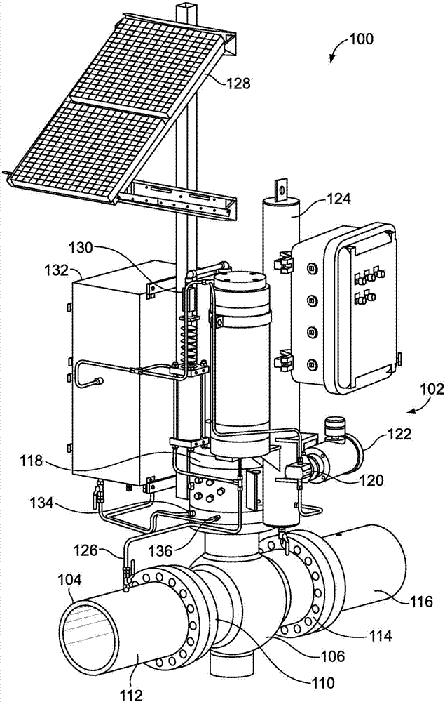
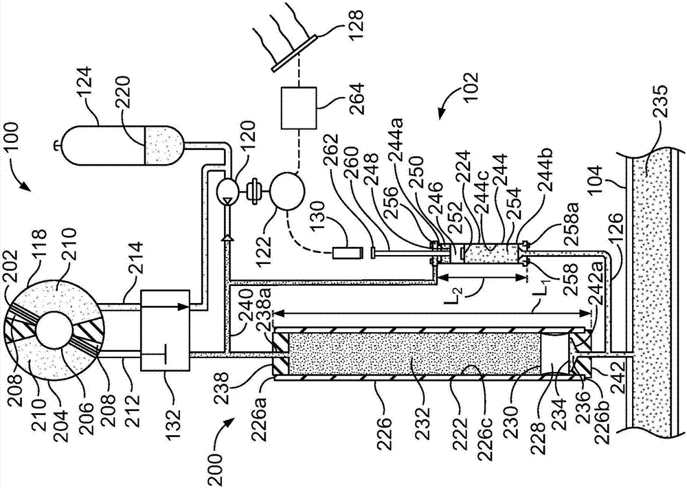
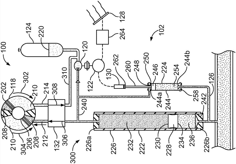
[0012] The control fluid power devices of the examples disclosed herein may be used in remote locations (eg, where pneumatic or electric power may not be available) to provide power (eg, hydraulic power) to process system components or equipment. For example, the control fluid power devices disclosed herein may be used to provide pressurized control fluid (e.g., hydraulic equipment) to devices such as cylinders, valve actuators, or other mechanisms that require high pressure fluid to operate (e.g., Hydraulic oil). Specifically, like oil and gas systems, example control fluid power devices disclosed herein use pressurized process fluid (eg, natural gas) to pressurize and / or deliver pressurized control fluid to process system components during operation. However, unlike conventional oil and gas systems, the example control fluid power devices disclosed herein do not vent process fluid to atmosphere. Instead, any process fluid used by the example control fluid power devices disc...


PUM


Abstract

The control fluid power apparatus (102) includes a first housing (226) having a first piston (228) defining a first chamber (232) and a second chamber (236), where the first chamber (232) receives a control fluid (220) and the second chamber (236) receives a process fluid (235) from a process system (104). The first chamber (232) is oriented above the second chamber (236) when the control fluid power apparatus (102) is coupled to a control valve assembly (100). A second housing (244) has a second piston (246) defining a third chamber (250) and a fourth chamber (254), where the third chamber (250) receives the control fluid (220) and the fourth chamber (254) receives the process fluid (235). The third chamber (250) is oriented above the fourth chamber (254) when the control fluid power apparatus (102) is coupled to the control valve assembly (100).

Description

technical field [0001] The present disclosure relates generally to power devices and, more particularly, to controlling fluid power devices and related methods. Background technique [0002] Gas-over-oil control valve systems are typically used in process systems at remote locations (e.g., offshore drilling, oil fields, natural gas transmission pipelines, etc.), where a power source (e.g., pneumatic power or electric power) may not be available of. Specifically, oil and gas control valve systems use high pressure process fluid flowing through process fluid lines (eg, natural gas) to power control valves (eg, actuators) instead of providing energy such as pneumatic power or electric power. In particular, oil and gas systems include hydraulic control fluid stored in external containers. The hydraulic control fluid is pressurized by delivering process fluid in a transfer line directly through and in contact with the hydraulic control fluid, which forces the hydraulic fluid in...

Claims


Application Information

Patent Timeline
Patent Type & Authority Applications(China)
IPC IPC(8): F16K31/122
CPCF16K31/1225F15B1/024F15B1/025F15B3/00F15B2201/20F15B2211/20515F15B2211/212F15B2211/275F15B1/04F15B13/0401F15B15/12F15B20/00F15B2201/00F15B2211/865
Inventor W·K·勒布兰克D·J·霍克
Owner EMERSON PROCESS MANAGEMENT VALVE AUTOMATION
Learn More