Bi-directional electromagnetic bench vice

A bench vice, electromagnetic technology, applied in the field of machinery, can solve the problems of low service life of thread teeth, deformation of thread teeth, low utilization rate, etc., and achieve the effects of enhancing service life, reducing force and high utilization rate

Inactive Publication Date: 2017-12-05
钱丽芳
View PDF1 Cites 3 Cited by
  • Summary
  • Abstract
  • Description
  • Claims
  • Application Information

AI Technical Summary

Problems solved by technology

[0002] At present, China's patent number CN201310720936.7 has announced a bench vise, including a frame, a main clamp, a main screw and a rotating handle. Connect the rotating handle, set a sub-clamp on both sides of the clamping force direction of the main clamp, extend the sub-screw from the sub-clamp and pass through the side of the opposite frame, and set a torque nut on the sub-screw outside the frame , when in use, firstly rotate the rotary handle to drive the main fixture to clamp the workpiece, then further clamp the workpiece, move the auxiliary fixtures on both sides of the main fixture to adjust its position, and finally rotate the torque nut to shrink the auxiliary screw, so as to obtain from the other two Clamp the workpiece at one point. Obviously, when the above-mentioned device is working, the main threaded rod first acts as a force bearing. After the main threaded rod receives the maximum pressure, the secondary threaded rod is used to bear the force. First, due to the main thread The first force on the rod leads to a large force, so the service life of its thread teeth is low, which can easily lead to deformation of the thread teeth. In the group of secondary threaded rods, there must be a problem of force first, and the force will cause the thread teeth to deform. In addition, because multiple groups of secondary threaded rods do not rotate at the same time, the pressure of each group of secondary threaded rods on the included angle will not Same, long time will lead to angle damage
[0003] In addition, the general bench vise is only one-way, and can only perform a single fastening function. When in use, the utilization rate is relatively low

Method used


Image

  • Bi-directional electromagnetic bench vice
  • Bi-directional electromagnetic bench vice
  • Bi-directional electromagnetic bench vice

Examples


Embodiment Construction

[0020] The following will clearly and completely describe the technical solutions in the embodiments of the present invention with reference to the accompanying drawings in the embodiments of the present invention. Obviously, the described embodiments are only some, not all, embodiments of the present invention. Based on the embodiments of the present invention, all other embodiments obtained by persons of ordinary skill in the art without making creative efforts belong to the protection scope of the present invention.

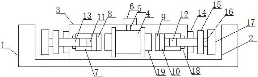
[0021] see figure 1, an embodiment provided by the present invention: a two-way electromagnetic bench vise, including a groove housing 1, the center of the upper surface of the groove housing 1 is provided with a working groove interval 2, and the groove housing The body 1 is provided with a main hollow shell 3 integrated with it at the center of the working groove section 2, and a 51 single-chip microcomputer 6 is installed on the top of the main hollow shell...


PUM


Abstract

The invention discloses a two-way electromagnetic bench vise, which comprises a groove shell, the center of the upper surface of the groove shell is provided with a working groove interval, and the groove casing is located in the working groove interval The center of the interior is provided with a main hollow shell with an integrated structure, a 51 single-chip microcomputer is installed on the top of the main hollow shell, and an iron core with a coil on the side is installed in the center of the main hollow shell , the control input end of the coil is connected to the control output end of the 51 single-chip microcomputer through wires. The invention can perform electromagnetic force resistance on the threaded rod used for fastening, thereby reducing the force on the thread structure during fastening and enhancing its service life. In addition, the device has an anti-overload protection mechanism, which can effectively prevent In addition, the device can simultaneously fix two sets of parts, so the utilization rate is high and the practicability is strong.

Description

technical field [0001] The invention relates to the technical field of machinery, in particular to a two-way electromagnetic bench vise. Background technique [0002] At present, China's patent number CN201310720936.7 has announced a bench vise, including a frame, a main clamp, a main screw and a rotating handle. Connect the rotating handle, set a sub-clamp on both sides of the clamping force direction of the main clamp, extend the sub-screw from the sub-clamp and pass through the side of the opposite frame, and set a torque nut on the sub-screw outside the frame , when in use, firstly rotate the rotary handle to drive the main fixture to clamp the workpiece, then further clamp the workpiece, move the auxiliary fixtures on both sides of the main fixture to adjust its position, and finally rotate the torque nut to shrink the auxiliary screw, so as to obtain from the other two Clamp the workpiece at one point. Obviously, when the above-mentioned device is working, the main th...

Claims


Application Information

Patent Timeline
Patent Type & Authority Applications(China)
IPC IPC(8): B25B1/24B25B1/00B25B1/10
CPCB25B1/24B25B1/00B25B1/10
Inventor 钱丽芳
Owner 钱丽芳
Why Eureka
Try Eureka