Solar LED street lamp with automatic cleaning function

A technology for LED street lamps and automatic cleaning, applied in cleaning methods and appliances, cleaning methods using tools, energy-saving lighting, etc., can solve problems such as high labor intensity, large water consumption, and poor cleaning effect, so as to improve work efficiency and reduce labor effect

Inactive Publication Date: 2017-12-05
陈菊蓉
View PDF0 Cites 7 Cited by
  • Summary
  • Abstract
  • Description
  • Claims
  • Application Information

AI Technical Summary

Problems solved by technology

However, the solar device of the solar street light is installed in the open air, which is heavily polluted by the outdoor environment. If the front of the solar device cannot be kept clean, the pollutants will cover the entire surface, which will affect the efficient use of solar energy, resulting in insufficient power supply for the street lamp, and the street lamp cannot continue to emit light. situation happened
The cleaning of photovoltaic panels of solar street lamps is usually carried out by the high-pressure water column of the cleaning vehicle. Since the cleaning personnel can only touch the photovoltaic panels under the condition of the ladder, the cleaning work is inconvenient, the labor intensity is high, the cleaning effect is poor, and the risk is high. The volume is large, the cost is high, and daily cleaning cannot be achieved

Method used


Image

  • Solar LED street lamp with automatic cleaning function
  • Solar LED street lamp with automatic cleaning function
  • Solar LED street lamp with automatic cleaning function

Examples


Embodiment Construction

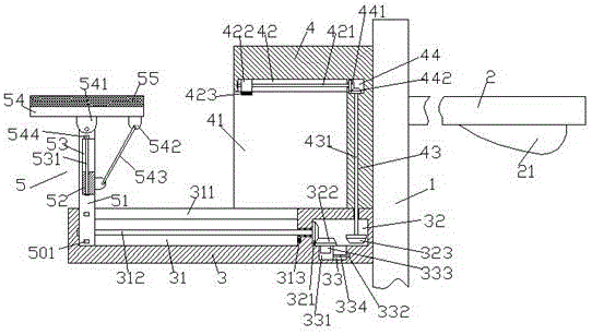
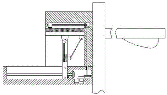
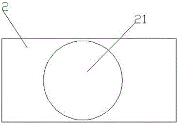
[0020] Such as figure 1 and image 3 As shown, a self-cleaning solar LED street lamp of the present invention includes a pillar 1, a pole 2 installed on the right side of the pillar 1, and a bracket 3 installed on the left side of the pillar 1. The bracket 3 A photovoltaic panel assembly 5 is provided on the upper left side, a cleaning part 4 is provided on the upper right side of the bracket 3, a first chute 31 is provided inside the left side of the bracket 3, and a first chute 31 is provided on the top of the first chute 31. A communication groove 311 extending along the first chute 31, a first cavity 32 is provided in the bracket 3 on the right side of the first chute 31, and a first cavity 32 is provided in the first chute 31 transversely. The first screw rod 312 extending to the left and right sides, the right extension section of the first screw rod 312 runs through the inner wall of the bracket 3 and is connected in a rotational fit, and the right end of the first scr...


PUM


Abstract

The invention discloses a solar LED street lamp with the automatic cleaning function. The solar LED street lamp comprises a supporting column, a supporting rod and a bracket, wherein the supporting rod is arranged on the right side of the supporting column, and the bracket is arranged on the left side of the supporting column; a photovoltaic panel assembly is arranged on the upper part of the left side of the bracket; a cleaning part is arranged on the upper part of the right side of the bracket; a first sliding groove is formed in the left side of the bracket; a communicating groove which extends along the first sliding groove is formed in the top of the first sliding groove; a first cavity is formed in the position, at the right side of the first sliding groove, in the bracket; a first screw which extends to the left side and the right side is transversely arranged in the first sliding groove; a right extending section of the first screw penetrates through the inner wall of the bracket and is connected to the inner wall of the bracket in a rotating mode; the tail end of the right side of the first screw extends into the first cavity and is provided with a first conical wheel; a second sliding groove is formed in the bottom of the first cavity; a second screw is arranged in the second sliding groove; the tail end of the right side of the second screw is in power connection with a first motor; the second screw is in threaded fit connection with a first sliding block; a second motor is arranged in the top of the first sliding block; and a main conical wheel which extends into the first cavity and is in rotating fit with the first cavity is arranged at the top of the second motor.

Description

technical field [0001] The invention relates to an LED street lamp, in particular to a self-cleaning solar LED street lamp. Background technique [0002] Solar energy is the most important renewable energy source, it does not produce any pollution and is free to use. In the latter half of the 20th century, many countries began to attach importance to the development and utilization of solar energy. In the 21st century, from solar water heaters to solar power generation, more and more solar energy utilization technologies are applied to people's production and life. Solar energy has become an indispensable energy source for social development. In recent years, street lamps powered by solar energy have appeared in many cities. The use of solar street lamps has greatly relieved the pressure on urban electricity consumption, and has been recognized by the society. It is likely to replace the original street lamp system. However, the solar device of the solar street light is in...

Claims


Application Information

Patent Timeline
Patent Type & Authority Applications(China)
IPC IPC(8): F21S9/03H02S20/30B08B1/00F21W131/103F21Y115/10
CPCB08B1/008F21S9/035F21W2131/103H02S20/30Y02B20/72Y02E10/50
Inventor 陈菊蓉
Owner 陈菊蓉
Why Eureka
Try Eureka