
Fully-automated flame adjuster

A fully automatic and fire-adjusting technology, applied in the field of machinery, can solve the problems of not being completely uniform in speed, not having a rejecting station in the detection equipment, and difficult to precisely control the station.

Active Publication Date: 2017-12-05
SHAODONG INTELLIGENT MFG INNOVATIVE INST
View PDF7 Cites 0 Cited by
  • Summary
  • Abstract
  • Description
  • Claims
  • Application Information

AI Technical Summary

Problems solved by technology

But the existing detection device is all sent to the station of the flame detector by the conveyor belt, and the following problems are transmitted by the conveyor belt: the conveyor belt is continuously running, and its rotating speed is not completely uniform (due to the voltage and current The instability and the resistance increase after the machine generates heat), it is impossible to be completely uniform, and the machine chooses to clamp and fix it to the flame detector station, which is generally controlled by a fixed time interval, so errors are prone to occur, making the lighter very It is difficult to completely align with the position of the flame detector, resulting in serious false detections
Some machines also use image recognition to judge the time to pick up the lighter, but one is the high cost, and the other is that it is difficult to accurately control the time, and there is still the problem that the lighter and the station are difficult to completely align
Secondly, after the inspection of lighters is completed, the defective products need to be removed, and they need to be placed in the finished product box. The existing inspection equipment does not have a removal station, because the station is difficult to accurately control, and it is also difficult to detect products. Precise placement in the product box

Method used


Image

  • Fully-automated flame adjuster
  • Fully-automated flame adjuster
  • Fully-automated flame adjuster

Examples


Embodiment 1

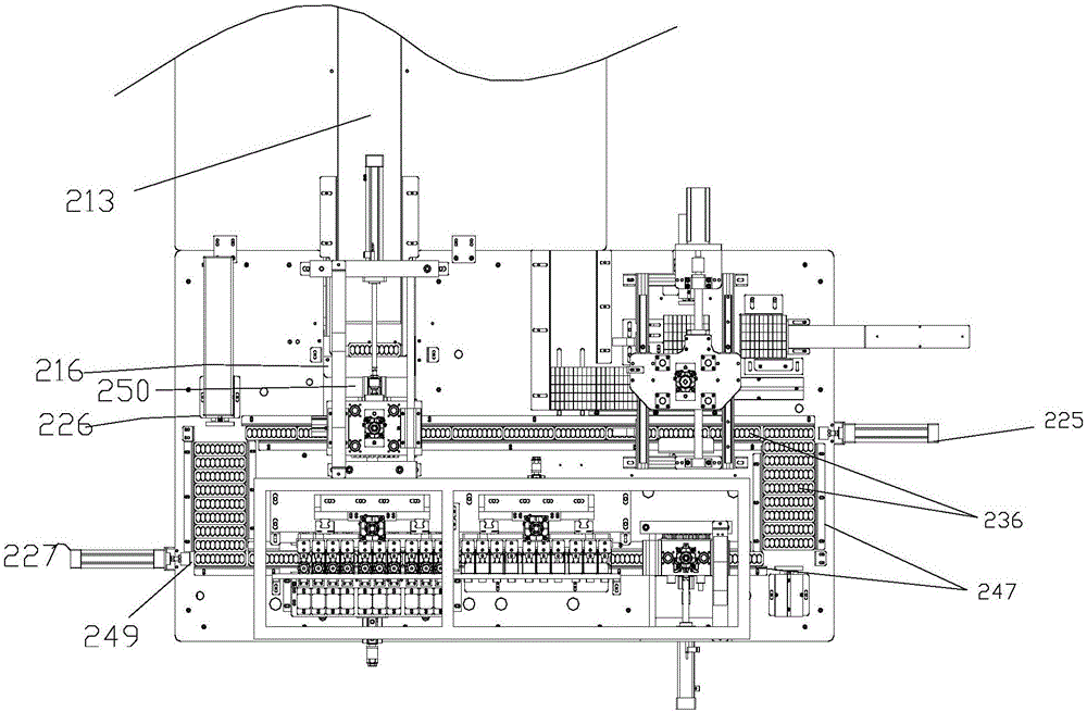
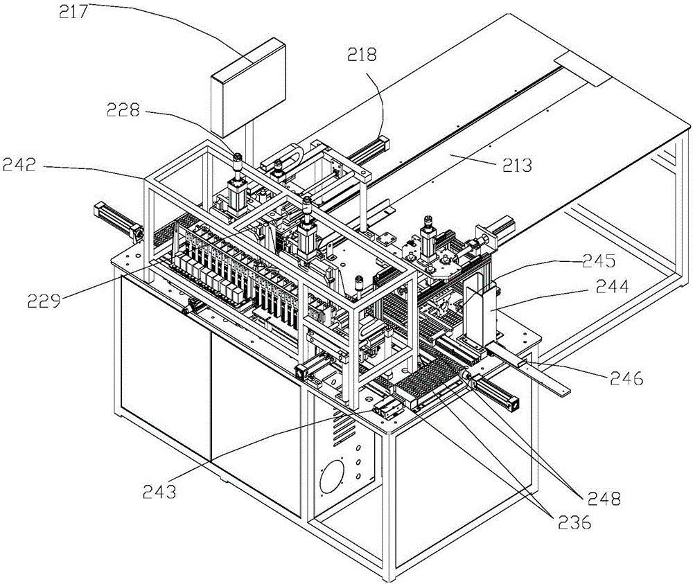
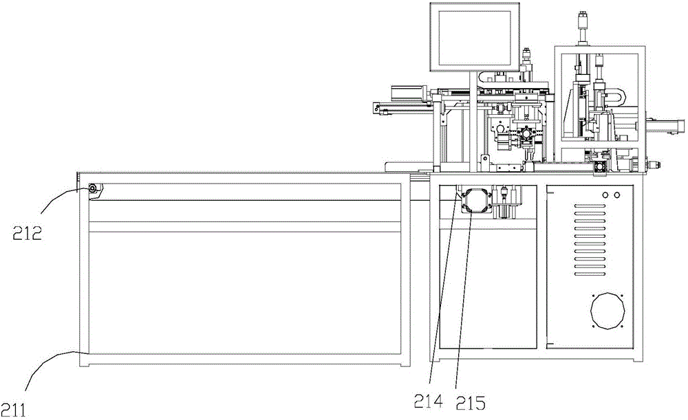
[0025] like Figure 1-2 The shown fully automatic lighter includes a material placement table 211, a rectangular rail 247 is installed on the material placement table 211, a material box 236 is placed inside the rectangular rail 247, and push-pull devices are respectively installed at the four corners of the rectangular rail 247 , along the material transmission direction, the push-pull device includes a first horizontal push-pull device, a first vertical push-pull device, a second horizontal push-pull device, and a second vertical push-pull device, and a gap 249 is provided on the rectangular track 247 corresponding to the push-pull device. A horizontal push-pull device, the first vertical push-pull device, the second horizontal push-pull device and the second vertical push-pull device cooperate to push so that the material box 236 moves along the rectangular track 247; The defective product rejecting mechanism is equipped with a feeding clamping mechanism in cooperation with...


PUM


Abstract

The invention discloses a fully-automated flame adjuster. The fully-automated flame adjuster comprises a material placing table and is characterized in that the material placing table is provided with a rectangular track, inside which a material box is arranged, and the four corners of the rectangular track are respectively provided with a push-pull device; in a material conveying direction, every push-pull device comprises a first horizontal push-pull device, a first vertical push-pull device, a second horizontal push-pull device and a second vertical push-pull device; a flame adjusting mechanism, a flame examination mechanism and a defective product eliminating mechanism are arranged long the rectangular track, and a feeding and clamping mechanism is matched with the rectangular track, and a feeding mechanism is mounted corresponding to the feeding and clamping mechanism. The fully-automated flame adjuster is simple in structure, convenient to use and capable of accurately moving a material case to ensure accuracy of flame examination and adjustment processes and avoiding false examination; meanwhile, by feeding and placing materials in a fully-automated mode, the fully-automated flame adjuster can achieve full automation of flame examination, flame adjustment and plate arrangement.

Description

technical field [0001] This patent belongs to the field of machinery, and in particular relates to a fully automatic lighter. Background technique [0002] When the lighter leaves the factory, it is necessary to adjust the flame height when it is on fire, so as to keep its ignition height consistent and meet the national requirements. At present, most manufacturers of lighters conduct inspections manually, but manual inspections are labor-intensive, work efficiency is low, and the inspection standards of workers are not easy to grasp, the detection accuracy is low, and the inspection standards cannot be unified and precise. For this reason, some manufacturers have developed automatic fire adjustment equipment, such as patent 200710152655, a disclosed fully automatic online detector for lighters, and a kind of lighter detection method and device disclosed in patent 201210412833. But the existing detection device is all sent to the station of the flame detector by the conveyo...

Claims


Application Information

Patent Timeline
IPC IPC(8): F23Q23/00
CPCF23Q23/00
Inventor 刘朋飞钱诚佳费明福梁玉鹏康文杰彭刚
Owner SHAODONG INTELLIGENT MFG INNOVATIVE INST
Learn More