Working Vehicle

A technology for operating vehicles and suction boxes, which is applied in agriculture, agricultural machinery and implements, and air cooling. It can solve the problems of cooling efficiency decline, increase cleaning and other maintenance procedures, and increase wind speed, so as to avoid the decline of cooling efficiency and improve the cooling efficiency. Cooling efficiency, effect of increasing air volume

Inactive Publication Date: 2017-12-08
KUBOTA LTD
View PDF15 Cites 2 Cited by
  • Summary
  • Abstract
  • Description
  • Claims
  • Application Information

AI Technical Summary

Problems solved by technology

In order to improve the cooling efficiency of the radiator, etc., it is conceivable to increase the speed of the rotationally driven cooling fan, thereby increasing the wind speed of the external air supplied to the radiator, etc. When the above measures are taken, dust such as straw chips is easy to adhere to, for example, the suction box On the contrary, it leads to a decrease in cooling efficiency and increases maintenance procedures such as cleaning.

Method used


Image

  • Working Vehicle
  • Working Vehicle
  • Working Vehicle

Examples


Embodiment Construction

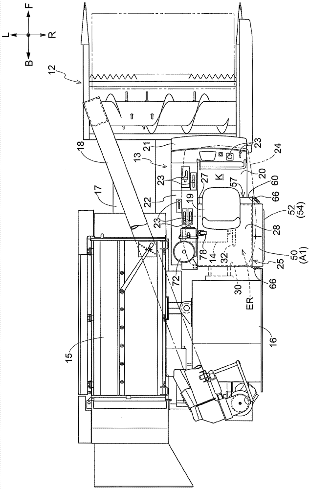
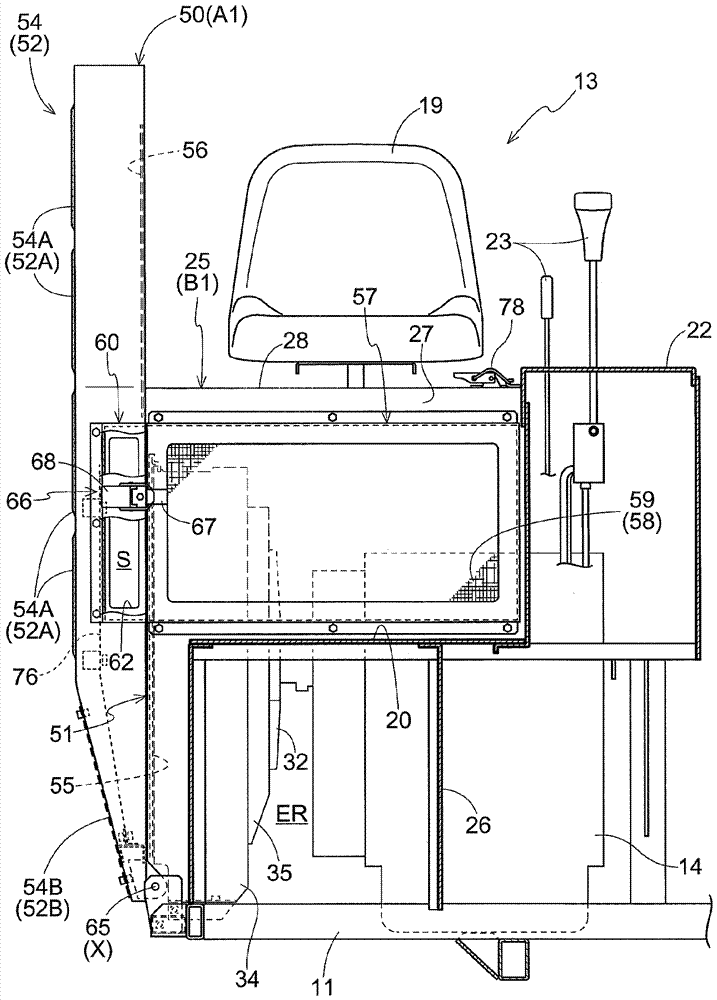
[0102] Hereinafter, an embodiment as an example of the present invention will be described with reference to the drawings.

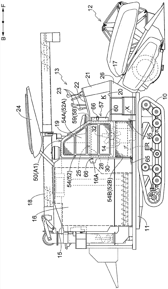
[0103] In the following description, regarding the running body of an ordinary combine harvester (an example of a "work vehicle"), figure 1 and figure 2 The direction of the arrow F shown is "front of the body", and the direction of the arrow B is "rear of the body", figure 2 The direction of the indicated arrow L is "the left side of the machine body", and the direction of the arrow R is "the right side of the machine body".

[0104] Such as figure 1 and figure 2 As shown, the traveling body of the ordinary type combine has a left and right pair of crawler-type traveling devices 10 and a body frame 11 assembled into a frame shape supported by the traveling devices 10 . At the front end part of the body frame 11, the reaping|reaping part 12 which reaps the stalk of planting grain is provided so that it can ascend and descend. The driving part 13 ...


PUM


Abstract

The present invention provides a working vehicle which can increase the wind quantity on the condition of not increasing the wind speed of an external gas supplied to the devices, such as a radiator, etc. The working vehicle comprises the radiator 31 for cooling the cooling water of an engine 14; a first gas absorbing box 50 arranged at the outer side of the machine body of the enclosed radiator 31 to allow the gas to pass and block the dust to pass; a cooling fan 32 arranged at inner side of the machine body of the radiator 31 and for cooling the radiator 31 by rotatably driving the external gas absorbed by the first gas absorbing box 50. The working vehicle also comprises a second gas absorbing box 57 allowing the gas to pass and blocking the dust to pass and communicated with the internal space S of the first gas absorbing box 50. By the rotary driving of the cooling fan 32, the external gas is absorbed by the second gas absorbing box and flows in the internal space S.

Description

technical field [0001] The present invention relates to work vehicles. Background technique [0002] A conventional work vehicle is described in Patent Document 1, for example. The work vehicle has: a radiator, which cools the cooling water of the engine; an air suction box, which is arranged outside the body of the radiator, and closes the outside of the body of the radiator in a state of allowing gas to pass through and preventing dust from passing through; and a cooling fan, which is provided Inside the body of the radiator, the radiator is cooled by taking in external air through the suction box through the rotary drive. [0003] In the prior art described above, since the external air is sucked in from only one suction box, the cooling efficiency of the radiator or the like may be low. In order to improve the cooling efficiency of the radiator, etc., it is conceivable to increase the speed of the rotationally driven cooling fan, thereby increasing the wind speed of th...

Claims


Application Information

Patent Timeline
Patent Type & Authority Applications(China)
IPC IPC(8): A01D41/12F01P1/00F01P11/12
CPCA01D41/12F01P1/00F01P11/12
Inventor 山本裕明光原昌希猿渡贤治松本健太
Owner KUBOTA LTD
Why Eureka
Try Eureka