
A method for laying load-carrying cables of catwalks for self-anchored suspension bridge construction

A self-anchored suspension bridge and bearing cable technology, applied in suspension bridges, bridge construction, bridges, etc., can solve problems such as low construction efficiency, many aerial operations, restricting construction progress, etc., to reduce time, ensure construction progress, and improve construction. The effect of efficiency

Active Publication Date: 2019-01-22
CHINA MCC17 GRP
View PDF1 Cites 0 Cited by
  • Summary
  • Abstract
  • Description
  • Claims
  • Application Information

AI Technical Summary

Problems solved by technology

[0003] The conventional method of installing the catwalk load-bearing cables is to use the suspension of the main cable of the suspension bridge to pull the catwalk load-bearing cables from the bridge bank to the main tower one by one for anchoring, or use a tugboat to tow one by one from the bridge bank to the main tower Connecting and anchoring at the above-mentioned method, the construction time of the above method is too much, the waterway is closed for a long time, and the construction efficiency is low, which directly restricts the construction progress.
[0004] At present, regarding the laying method of catwalk load-carrying cables for the construction of self-anchored suspension bridges, patent designs with similar names have been retrieved, such as "Construction of a Space Self-anchored Suspension Cable System" published by the State Patent Office of China on April 29, 2009 Method", publication number CN101418542A and "Construction Method for Integration of Pilot Cable Crossing the River and Traction System" published on October 10, 2012. Neither of the two similar construction patents specifically describes the laying method of the catwalk load-bearing cables.

Method used


Image

  • A method for laying load-carrying cables of catwalks for self-anchored suspension bridge construction
  • A method for laying load-carrying cables of catwalks for self-anchored suspension bridge construction
  • A method for laying load-carrying cables of catwalks for self-anchored suspension bridge construction

Examples


Embodiment Construction

[0038] The following will clearly and completely describe the technical solutions in the embodiments of the present invention with reference to the accompanying drawings in the embodiments of the present invention. Obviously, the described embodiments are only some, not all, embodiments of the present invention. Based on the embodiments of the present invention, all other embodiments obtained by persons of ordinary skill in the art without making creative efforts belong to the protection scope of the present invention.

[0039] Unless otherwise defined, the technical terms or scientific terms used herein shall have the usual meanings understood by those having ordinary skill in the art to which the present disclosure belongs. The terms "upper", "lower", "left", and "right" used in the specification and claims of this patent application are only used to indicate the relative positional relationship. When the absolute position of the described object changes, the relative positio...


PUM


Abstract

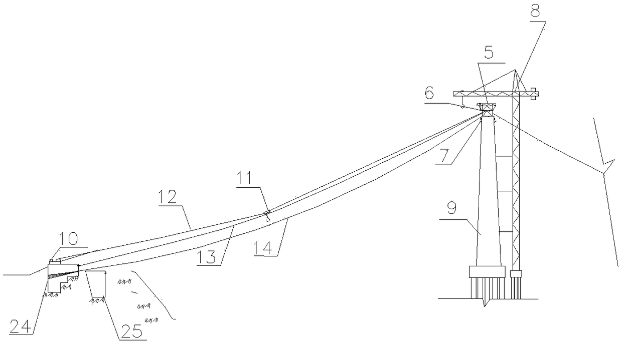
The invention discloses a self-anchorage laying method for catwalk bearing cables for suspension bridge construction and relates to the field of bridge construction. The self-anchorage laying method is characterized in that by means of a suspending crane for laying of main cables, a tower crane for construction of a main tower and a main tower upper tower top steel platform for hoisting of cable saddles, according to the set groups of the catwalk bearing cables, the catwalk bearing cables are conveyed to the position below the main tower through a tugboat in advance, then through hoisting of the tower crane and the suspending crane, aerial laying of the catwalk bearing cables is achieved, and the catwalk bearing cables are fixed to the corresponding fixing points; and in a similar way, laying of the other catwalk bearing cables of a suspension bridge is completed, so that aerial laying work of the catwalk bearing cables is completed. The self-anchorage laying method comprises the construction steps of (1) construction preparation, (2) catwalk bearing cable fitting up, (3) aerial cable laying and (4) catwalk bearing cable adjustment. According to the self-anchorage laying method for the catwalk bearing cables for suspension bridge construction, the aerial operation and waterway navigation closure time needed by constructors for laying the catwalk bearing cables can be reduced, the construction efficiency is improved, the construction progress is ensured, and the good economic and social benefits are achieved.

Description

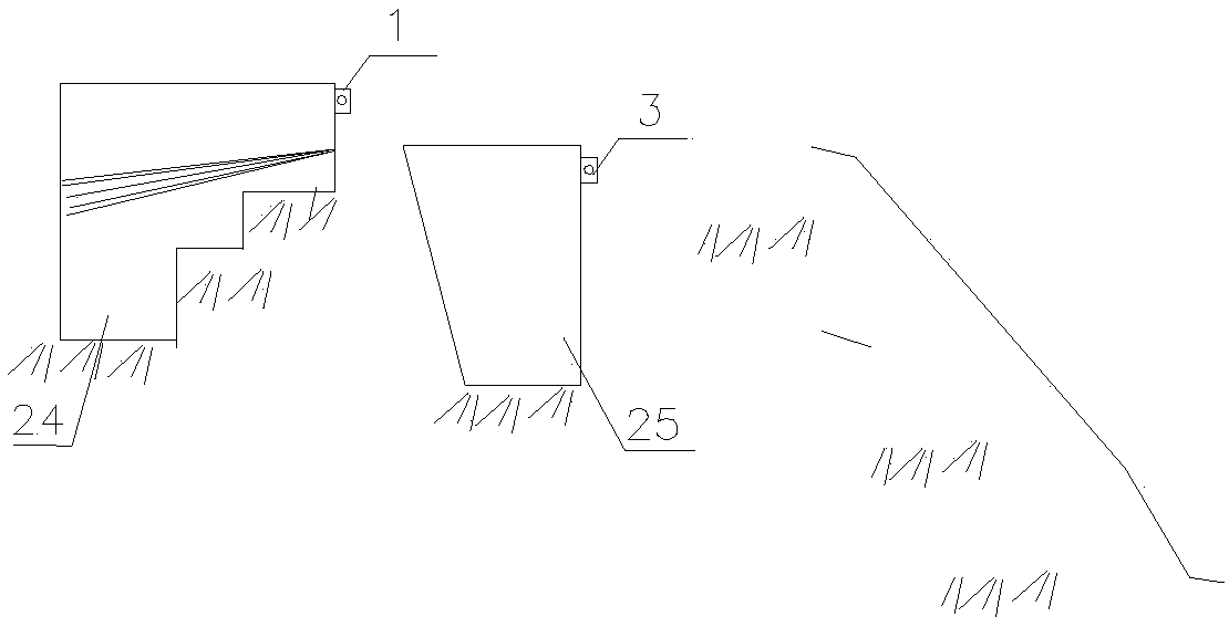
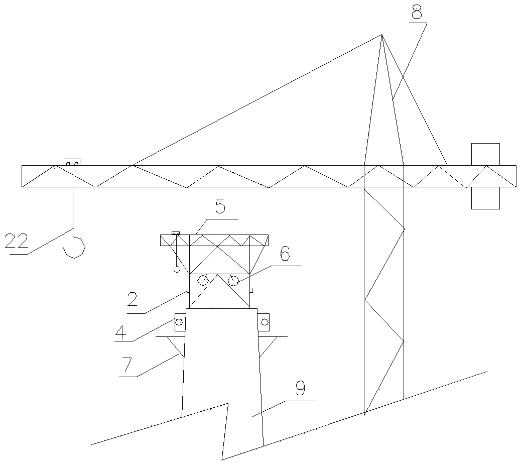
technical field [0001] The invention relates to the field of bridge construction, in particular to a method for laying catwalk bearing cables for self-anchored suspension bridge construction. Background technique [0002] The catwalk is a linear temporary construction aerial platform under the main cable of the suspension bridge and parallel to the main cable. The catwalk load-bearing cable is the core component of the construction platform. Anchored on the anchor bases at the main tower end and the bridge bank end, the centerline of the formed load-bearing cable is about 1500mm lower than the centerline of the main cable, so as to facilitate construction personnel to complete such as cable strand traction, strand adjustment, shaping into saddles, extrusion, etc. on the catwalk. Tightening, cable clamp and sling installation, box girder hoisting, main cable winding, protective coating and other construction tasks. [0003] The conventional method of installing the catwalk l...

Claims


Application Information

Patent Timeline
Patent Type & Authority Patents(China)
IPC IPC(8): E01D21/00E01D11/02
CPCE01D11/02E01D21/00
Inventor 朱道付金仁才孔炯郑治飞
Owner CHINA MCC17 GRP
Learn More