
Method used for improving measurement accuracy of stagnation total temperature probe

A probe measurement and accuracy technology, applied in the field of improving the measurement accuracy of stagnant total temperature probes, can solve the problems of increasing airflow temperature pulsation, increasing airflow velocity, uneven distribution, etc., to improve measurement accuracy and reduce speed Error, the effect of uniform airflow distribution

Active Publication Date: 2017-12-08
BEIHANG UNIV
View PDF5 Cites 3 Cited by
  • Summary
  • Abstract
  • Description
  • Claims
  • Application Information

AI Technical Summary

Problems solved by technology

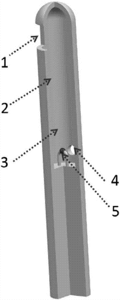
[0010] Although the stagnant total temperature probe has many advantages in the measurement of the total temperature of the high-speed airflow, due to the lack of understanding and analysis of the characteristics of the flow structure in the stagnant chamber, there are still many shortcomings in the current technology.
First, in the currently used technology, the airflow vertically impacts the inner wall of the stagnation chamber and forms multiple separation zones in the stagnation chamber. stagnation effect
Second, due to the influence of the separation bubble in the stagnation chamber, the flow of the airflow in the stagnation chamber has a strong three-dimensional unsteadiness, which makes the airflow velocity V around the measuring end vary in size and the distribution is very uneven
Third, this strong three-dimensional unsteadiness makes the pulsation of the airflow flowing through the measurement end larger, which increases the pulsation of the measured airflow temperature and reduces the temperature measurement accuracy

Method used


Image

  • Method used for improving measurement accuracy of stagnation total temperature probe
  • Method used for improving measurement accuracy of stagnation total temperature probe
  • Method used for improving measurement accuracy of stagnation total temperature probe

Examples


Embodiment Construction

[0028] The flow control method of the invention can be used for flow control in various stagnation chambers including stagnation total temperature probes and shielded total temperature probes.

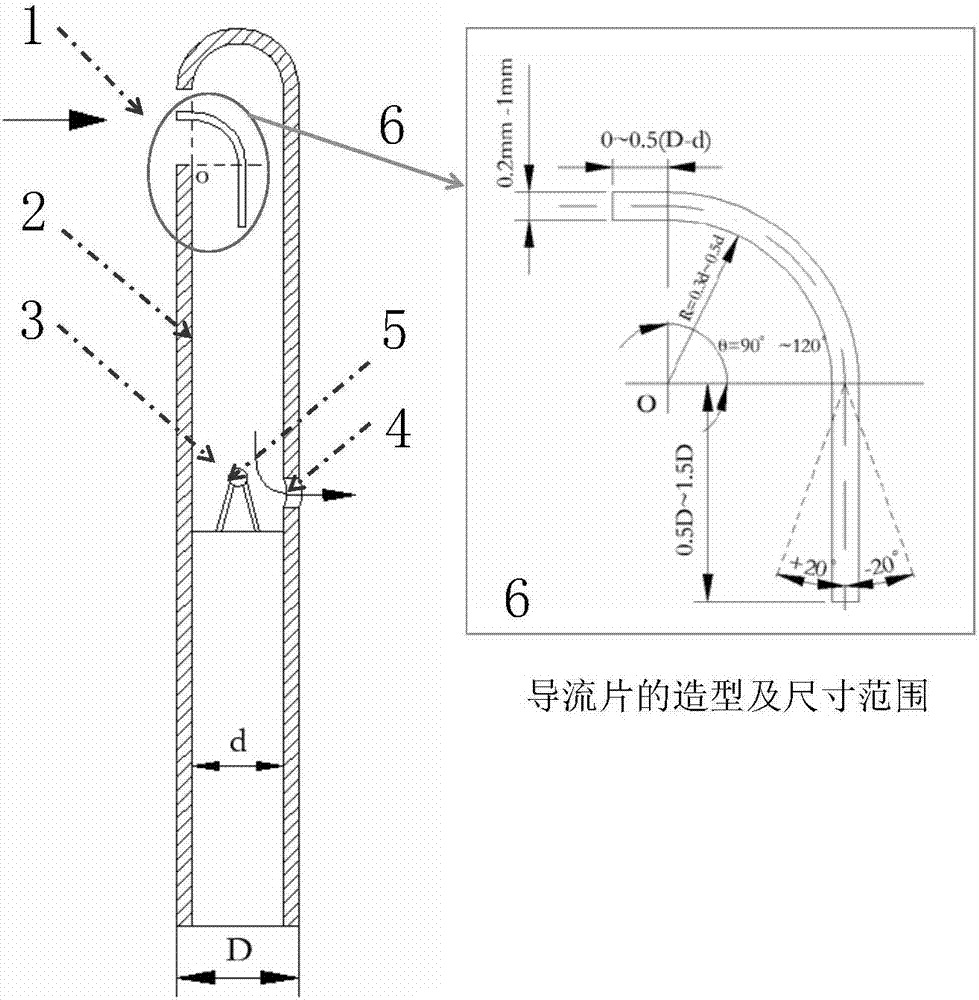
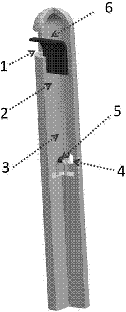
[0029] like figure 2 and image 3 As shown, in the embodiment of the present invention, a deflector 6 is arranged between the stagnation cover inlet 1 of a stagnation total temperature probe and the stagnation inner wall 2, and the area of ​​the stagnation cover inlet 1 is divided into two parts of 1:2. In part, the deflector 6 is fixed by the inner wall 2 of the stagnation chamber.

[0030] The extended length of the deflector 6 in the stagnation chamber 3 is determined according to the length and diameter of the stagnation chamber 3 and the actual flow inside the stagnation chamber. The length of the flow sheet.

[0031] The stagnation type total temperature probe with deflector designed by the method provided by the present invention is as follows: image 3 shown.

[0032] Num...


PUM

PropertyMeasurementUnit
thicknessaaaaaaaaaa

Abstract

The invention relates to a method used for improving the measurement accuracy of a stagnation total temperature probe. Guide pieces are arranged in a stagnation cover inlet and in a stagnation chamber. The stagnation cover inlet is divided into two parts up and down. According to the invention, indoor air flow can be stagnated, so as to make the air flow velocity distribution around the measurement end of the stagnation total temperature probe uniform; the pulsation of the air flow is reduced; the velocity of air flow shocking the measurement end can be obviously reduced; the velocity errors of the stagnation total temperature probe are reduced; and the measurement accuracy of the stagnation total temperature probe is improved.

Description

technical field [0001] The invention relates to a method for improving the measurement accuracy of a stagnation total temperature probe, in particular to the measurement of total temperature of aero-engines or gas turbines and high-speed airflow in the field of aerospace. Background technique [0002] The temperature indicated by the total temperature probe when measuring the airflow temperature is essentially the temperature of the part of the airflow that impacts its measuring end and exchanges heat with it. total air temperature T t From static temperature T s and dynamic temperature T d T t =T s +T d , where the magnitude of the dynamic temperature is positively correlated with the quadratic of the air velocity, as shown in formula (1). It can be seen that if the airflow flowing through the temperature measuring end of the total temperature probe has a relatively high velocity, the temperature value indicated by the total temperature probe will be quite different f...

Claims


Application Information

Patent Timeline
Patent Type & Authority Applications(China)
IPC IPC(8): G01K13/02G01K13/024
CPCG01K13/028
Inventor 张伟昊杨伟平邹正平刘火星王效葵
Owner BEIHANG UNIV
Learn More