
LED Display screen box lock structure

A technology of LED display screen and locking structure, applied in the direction of instruments, identification devices, etc., can solve the problems of precision error, inconvenient operation, complex structure, etc., and achieve the effect of improving the accuracy of angle splicing, convenient operation and simple structure

Active Publication Date: 2017-12-08
UNILUMIN GRP
View PDF10 Cites 5 Cited by
  • Summary
  • Abstract
  • Description
  • Claims
  • Application Information

AI Technical Summary

Problems solved by technology

[0002] At present, arc-shaped splicing screens mostly use arc-shaped guide rails to achieve arc-shaped splicing, and the accuracy error of the fit gap of the arc-shaped guide rails will be magnified dozens of times in the tangential direction of the arc, making it difficult to ensure the splicing accuracy of the display screen. The force direction is consistent with the adjustment direction, so the existing arc guide rail must have a locking device to ensure that the adjusted angle is fixed, and its structure is relatively complicated and inconvenient to operate
[0003] In the prior art, angle pads are also used to solve the problem of precision error, but one angle pad can only adjust one angle, and different angle pads must be replaced to adjust different angles, which increases the cost and is inconvenient to use

Method used


Image

  • LED Display screen box lock structure
  • LED Display screen box lock structure
  • LED Display screen box lock structure

Examples


Embodiment

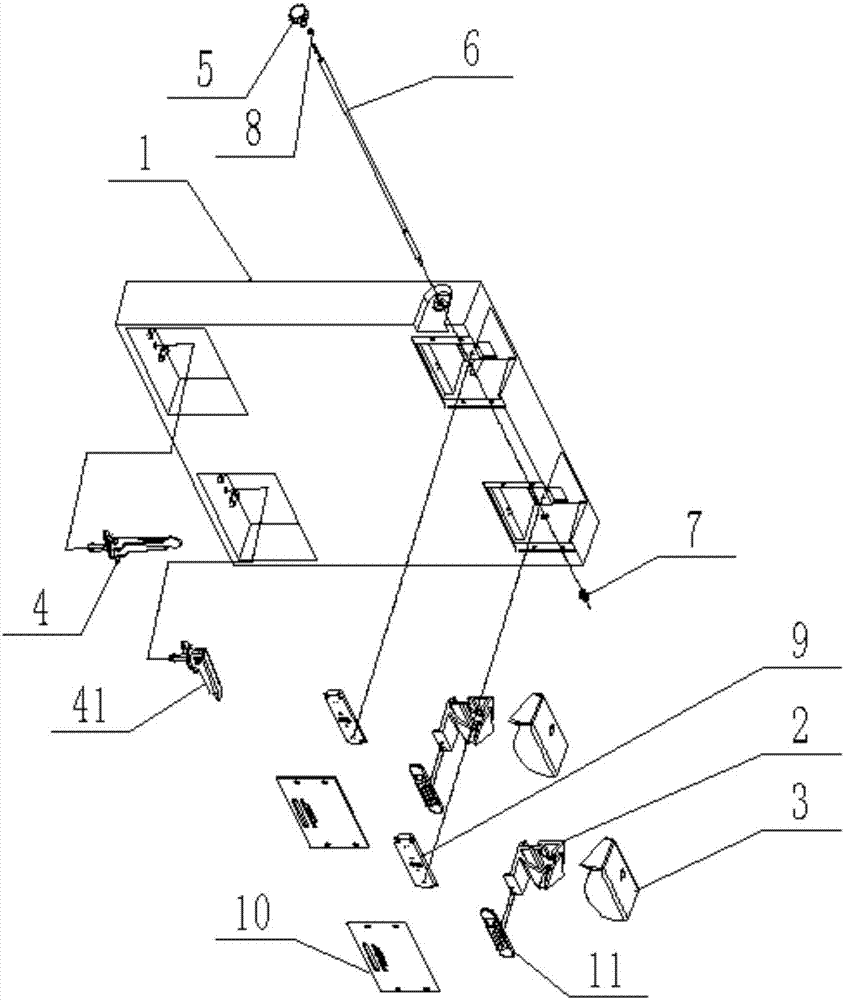
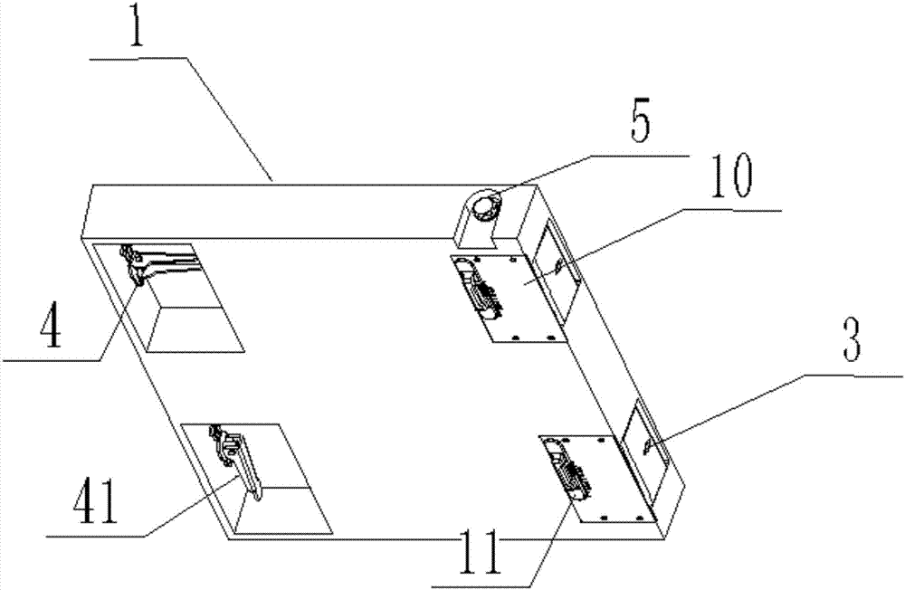
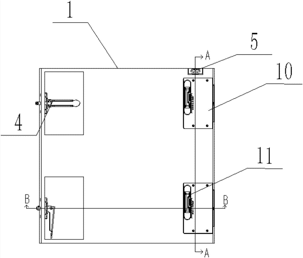
[0030] Such as figure 1 As shown, it is an exploded schematic diagram of the locking structure of the LED display box of the present invention, figure 2 It is a combination diagram of the locking structure of the LED display box of the present invention, image 3 It is a front view of an LED display cabinet lock structure, Figure 4 for image 3 A-A sectional view in, Figure 5 for image 3 B-B cross-sectional view in the figure; in this embodiment, a LED display cabinet lock structure, including: adjustment block 2, angle block 3 and curved surface guide rail 14, the adjustment block 2, angle block 3 and curved surface guide rail 14 are all Set on the box 1, the adjustment block 2 is connected to the angle block 3 through a curved guide rail 14, and when the adjustment block 2 moves linearly, the angle block 3 is driven to rotate by the curved guide rail 14.

[0031] In this embodiment, the linear motion of the adjustment block 2 is transformed into the rotational motio...


PUM


Abstract

The invention belongs to the technical field of displays and discloses an LED display screen box lock structure, comprising adjusting blocks, angle blocks and curved guide rails; all the adjusting blocks, the angle blocks and the cured guide rails are arranged on a box body; the adjusting blocks are connected with the angle blocks through the curved guide rails; when the adjusting blocks are in linear motion, the angle blocks are driven to rotate through the curved guide rails; the box body is also provided with lock locking structures corresponding to the angle blocks; the angle blocks on one box body cooperate with lock locking structures of another box body to adjust the angle of the two box bodies; linear motion of the adjusting blocks is converted into rotational motion of the angle blocks through the curved guide rails so as to arrive at angle adjustment, and angle splicing precision is improved; the LED display screen box lock structure is simple in structure and convenient to operate, and has no need for machining so that the cost is greatly reduced.

Description

technical field [0001] The invention relates to the technical field of displays, in particular to a locking structure of an LED display box. Background technique [0002] At present, arc-shaped splicing screens mostly use arc-shaped guide rails to achieve arc-shaped splicing, and the accuracy error of the fit gap of the arc-shaped guide rails will be magnified dozens of times in the tangential direction of the arc, making it difficult to ensure the splicing accuracy of the display screen. The force direction is consistent with the adjustment direction, so the existing arc guide rail must have a locking device to ensure that the adjusted angle is fixed, and its structure is relatively complicated, and the operation is inconvenient. [0003] In the prior art, angle pads are also used to solve the problem of precision error, but one angle pad can only adjust one angle, and different angle pads must be replaced to adjust different angles, which increases the cost and is inconven...

Claims


Application Information

Patent Timeline
Patent Type & Authority Applications(China)
IPC IPC(8): G09F9/302G09F9/33
CPCG09F9/3026G09F9/33Y02E10/50
Inventor 贺金锋
Owner UNILUMIN GRP
Learn More